Pseudo-moons Orbit Earth
Sky And Telescope, 30 December 2011
http://www.skyandtelescope.com/news/Pseudo-moons-Orbit-Earth-136435308.html
Earth may be going steady with the Moon, but it has a bit of a wanderer’s relationship with some other nearby objects. A study by an international trio of scientists suggests that, at any given time, there is at least one meter-sized mini asteroid temporarily orbiting our planet. Caught from the population of near-Earth objects (NEOs), the “satellite” completes on average three whirls around us in less than a year before the planet and meteoroid go their separate ways.
Friday, December 30, 2011
Thursday, December 29, 2011
Online: How to Design, Build, and Test Small Liquid-Fuel Rocket Engines
HOW to DESIGN, BUILD and TEST SMALL LIQUID-FUEL ROCKET ENGINES
Risacher.org, 29 December 2011
http://www.risacher.org/rocket/
also
http://www.cientificosaficionados.com/libros/cohetes.pdf [PDF, 6.3M]
This excellent book, written by Leroy J. Krzycki in the 1960's provides a good theoretical and practical overview of developing your own liquid propellant rocket motors. Although dated, it provides timeless theoretical coverage in an understandable fashion. It covers all aspects from the motor to a suitable test system.
Wednesday, December 28, 2011
Online: Conceptual Design and Analysis of a Small and Low Cost Launch Vehicle
Conceptual Design and Analysis of a Small and Low Cost Launch Vehicle
Georgia Tech, May 2005
http://www.ssdl.gatech.edu/papers/mastersProjects/TayaK-8900.pdf
In this publication, the authors "treat [Microcosm's] Sprite launch vehicle as an example of small and low-cost launch vehicle. The goal of project is to analyze its design concept, confirm performance, and refine its design."
Sunday, December 25, 2011
Online: How Small Can a Launch Vehicle Be?
How Small Can a Launch Vehicle Be?
Lawrence Livermore, 10 July 2005
https://e-reports-ext.llnl.gov/pdf/321763.pdf [PDF, 183K]
This classic document reviews the background requirements of launching a vehicle to low Earth orbit, focusing on the issue of lower bounds on the size of the vehicle.
ABSTRACT
Trajectory simulations from Earth to orbit indicate comparative velocity requirements depending on vehicle size, for several propellant options. Smaller vehicles are more affected by drag, resulting in steeper trajectories that require more total velocity. Although they are technically challenging, launch vehicles smaller than 1 ton are not ruled out by the nature of ascent trajectories.
Saturday, December 24, 2011
Online: NASA SPACE VEHICLE DESIGN CRITERIA SP-8000
NASA SPACE VEHICLE DESIGN CRITERIA SP-8000
arocketry.net, 24 December 2011
http://www.arocketry.net/sp-8000.html
If you weren't already aware of them, Nasa produced a whole series of technical tutorials on different aspects of rocket design. If you haven't checked them out, I highly recommend doing so. You'll find everything from propulsion design, propellant feed system design, and a number of other highly-practical tutorials.
Thursday, December 22, 2011
Book: Design of liquid propellant rocket engines
Design of Liquid Propellant Rocket Engines, 2nd Edition
NASA NTRS, 19 December 2011
http://hdl.handle.net/2060/19710019929 [ PDF, 45M ]
This is the classic Huzel and Huang "Design of Liquid Propellant Rocket Engines". It covers rocket theory and has good design examples.
NASA NTRS, 19 December 2011
http://hdl.handle.net/2060/19710019929 [ PDF, 45M ]
This is the classic Huzel and Huang "Design of Liquid Propellant Rocket Engines". It covers rocket theory and has good design examples.
Wednesday, December 21, 2011
Monday, December 19, 2011
News: Build a DIY Spacecraft is a Daunting Task
To Build a DIY Spacecraft is a Daunting Task and, Not Surprisingly, Getting It Up Where It Belongs, in Space, Is No Less of a Problem
Wired, 19 December 2011
http://www.wired.com/wiredscience/2011/12/to-build-a-diy-spacecraft-is-a-daunting-task/
A ballistic missile is suddenly a simpler, much more affordable, single-stage solution to flying out of Earth’s atmosphere. The performance can be increased far beyond that of a winged space plane. And that’s it.
Sunday, December 18, 2011
Specific Impulse
Specific Impulse is one of the two key method of measuring the performance of a rocket system (the other being mass ratio). Understanding Specific Impulse is one of the most important things to know to understand orbital rockets.
DEFINITION
Just like one of the measures of the efficiency of a car is miles per hour, rockets have their own measure of efficiency, Specific Impulse (or Isp), measured in seconds.
Specific Impulse (or Isp) is the number of seconds that one unit weight of propellant will produce one unit force of thrust. The equation for calculating Isp derived from its definition is:
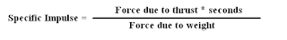 Since there is a unit of force in both the numerator and denominator, they cancel out to leave just seconds.
In both American Standard and Metric, the same formula applies. In metric, you can
just put the thrust force in Newtons and convert the mass of the propellant into its
weight by multiplying by the gravitational acceleration (g = 9.80665 m/s^2) because
Force = mass * acceleration:
 Knowing that a propellant can provide 200 seconds of 1 pound of thrust with one
pound of propellant, one can also determine that the propellant will produce
400 seconds of 1/2 pound of thrust with one pound of propellant.
Sometimes, Metric users will just use Mass instead of Weight and so the
value of Metric Specific Impulse is off by a constant factor of 9.8. You'll
see that value used in the literature as well.
ISP EQUATION
The rocket force equation is:
 Where:
 Where:
EXAMPLES AND REASONABLE RANGES FOR ISP
The following table shows some representative values for different propellant combinations and their vacuum Isp.
 But, a rocket motor behaves differently, having different Isp at different altitudes and ambient pressures. The following graph shows the Isp characteristic of a rocket through different atmospheric conditions. It is for a LOX-Isopropyl Alchohol motor with a 1.65:1 mixture ratio, a 3.12:1 expansion ratio and a chamber pressure of 250 PSI (with 90% combustion efficiency).

As can be seen, the Isp varies greatly throughout the flight regime. At sea level, the Isp is about 213 seconds, but by the time it is at 25,000 feet, the Isp has gone up to about 253 seconds. This is with no change of propellant flow characteristics or change of combustion pressure. This is solely due to the effect of the nozzle throughout its flight regime.
Therefore, since a rocket in flight spends more of its flight time at higher altitude, it will see a higher average Isp throughout its flight than its sea level value. This is an important thing to understand and exploit in designing rocket boosters.
DEFINITION
Just like one of the measures of the efficiency of a car is miles per hour, rockets have their own measure of efficiency, Specific Impulse (or Isp), measured in seconds.
Specific Impulse (or Isp) is the number of seconds that one unit weight of propellant will produce one unit force of thrust. The equation for calculating Isp derived from its definition is:
In both American Standard and Metric, the same formula applies. In metric, you can
just put the thrust force in Newtons and convert the mass of the propellant into its
weight by multiplying by the gravitational acceleration (g = 9.80665 m/s^2) because
Force = mass * acceleration:
pound of propellant, one can also determine that the propellant will produce
400 seconds of 1/2 pound of thrust with one pound of propellant.
Sometimes, Metric users will just use Mass instead of Weight and so the
value of Metric Specific Impulse is off by a constant factor of 9.8. You'll
see that value used in the literature as well.
ISP EQUATION
The rocket force equation is:
 Force  = the thrust of the rocket
 mdot   = the mass flow rate through the rocket
 Ve     = the exhaust velocity out of the nozzle exit
 Pe     = the pressure at the nozzle exit
 po     = the ambient operating pressure
 Ae     = the area at the nozzle exit
Since Force is part of the Isp equation, we can subsitute this force equation into the Isp equation to show some important relationships between the factors that produce the thrust of a rocket and its Isp:
 Isp = the specific impulse
 mdot = the mass flow rate
 Ve   = the exhaust velocity
 Pe   = the pressure at the nozzle exit
 po   = the ambient operating pressure
 Ae   = the area of the nozzle exit
 g    = the acceleration of gravity
As can be seen, the pressure of the ambient operating environment affects the Isp of the rocket.
EXAMPLES AND REASONABLE RANGES FOR ISP
The following table shows some representative values for different propellant combinations and their vacuum Isp.


As can be seen, the Isp varies greatly throughout the flight regime. At sea level, the Isp is about 213 seconds, but by the time it is at 25,000 feet, the Isp has gone up to about 253 seconds. This is with no change of propellant flow characteristics or change of combustion pressure. This is solely due to the effect of the nozzle throughout its flight regime.
Therefore, since a rocket in flight spends more of its flight time at higher altitude, it will see a higher average Isp throughout its flight than its sea level value. This is an important thing to understand and exploit in designing rocket boosters.
Saturday, December 17, 2011
News: Space: The Next Business Frontier
Space: The Next Business Frontier
Wall Street Journal, 17 December 2011
http://online.wsj.com/article/SB10001424052970203413304577086660050261668.html?mod=googlenews_wsj
"We can put satellites into space at a fraction of the price that it currently costs," he says—and Virgin is working with a "tiny little" company (the name of which hasn't yet been publicly disclosed) to do just that. "Whereby, for instance, [on] Google, you can see what's going on six months ago, these satellites will be able to see what's going on right now."
Thursday, December 15, 2011
News: Stratolaunch: a contrarian view
Stratolaunch: a contrarian view
NewSpace Journal, 15 December 2011
http://www.newspacejournal.com/2011/12/15/stratolaunch-a-contrarian-view/
However, the more I thought about it later Tuesday and into yesterday, the more questions developed in my mind about this venture. From a technical standpoint, I don’t doubt that the Stratolaunch team has the ability to develop what they’re proposing, particularly given the experience of Scaled and SpaceX. Yes, there will be complications along the way, but these companies are as well positioned as any to deal with them.
Tuesday, December 13, 2011
News: Stratolaunch Announces Formation
Stratolaunch Systems
Stratolaunch Systems, 13 December 2011
http://stratolaunchsystems.com/
Stratolaunch Systems, a Paul G. Allen project, is developing an air-launch system that will revolutionize space transportation by providing orbital access to space at lower costs, with greater safety and more flexibility. Delivering payloads in the 10,000lbm class into low earth orbit, the system allows for maximum operational flexibility and payload delivery from several possible operational sites, while minimizing mission constraints such as range availability and weather.
Monday, December 12, 2011
LEO on the Cheap
LEO on the Cheap
Quarkweb, 12 December 2011
http://www.quarkweb.com/nqc/lib/gencoll/
This is a good book on some approaches to lowering the cost of access to space.
Quarkweb, 12 December 2011
http://www.quarkweb.com/nqc/lib/gencoll/
This is a good book on some approaches to lowering the cost of access to space.
Sunday, December 11, 2011
News: Buried in space? Virginia may help pay for it
Buried in space? Virginia may help pay for it
LA Times, 11 December 2011
http://www.latimes.com/news/nationworld/nation/la-na-space-burial-20111209,0,993488.story
A bill intended as a boost for the Mid-Atlantic Regional Spaceport would provide a state income tax deduction.
LA Times, 11 December 2011
http://www.latimes.com/news/nationworld/nation/la-na-space-burial-20111209,0,993488.story
A bill intended as a boost for the Mid-Atlantic Regional Spaceport would provide a state income tax deduction.
Friday, December 9, 2011
News: $5,000 Kit to Send Your Own Rocket to the Moon
$5,000 Kit to Send Your Own Rocket to the Moon
Space.com, 9 December 2011
http://www.space.com/13884-cheap-moon-rocket-balloon.html
Launching the rocket into space from its balloon is expected to be as easy as "fire and forget," but a simple ham radio aboard the rocket could beam telemetry data back to the human user on the ground. True to the DIY spirit, the team also plans to use mostly commercially available parts for building the rocket.
Thursday, December 8, 2011
News: So, You Got a Space Rocket But Nowhere To Launch It?
So, You Got a Space Rocket But Nowhere To Launch It?
Wired, 8 December 2011
http://www.wired.com/wiredscience/2011/12/so-you-got-a-space-rocket-but-nowhere-to-launch-it/
So, you want to build a space rocket or maybe you already have? Unless you represent a government agency, have access to Californian deserts or Siberia you might soon realize you have problem. The problem faced by everyone building rockets.
Where in hell are you going to launch it?
[...]
Water!
Wednesday, December 7, 2011
News: Boeing Receives US Air Force Reusable Booster System Contract
Boeing Receives US Air Force Reusable Booster System Contract
Boeing, 7 December 2011
http://boeing.mediaroom.com/index.php?s=43&item=2058
The Boeing Company [NYSE: BA] has received a $2 million contract from the U.S. Air Force Research Laboratory (AFRL) to define requirements and design concepts for the Reusable Booster System (RBS) Flight and Ground Experiments program. This program will enhance space launch capability by providing a reliable, responsive and cost-effective system.
Boeing will begin work immediately on the requirements and concepts for the RBS demonstration vehicle, called RBS Pathfinder, at the company's Huntington Beach facility. Under the indefinite delivery, indefinite quantity contract, three teams will compete for a follow-on task order to develop the vehicle and conduct a flight test.
Tuesday, December 6, 2011
News: Armadillo Launches Stig A to 26 Miles
Armadillo Aerospace Successfully Lauches a Sounding Rocket from Spaceport America
Universe Today, 6 December 2011
http://www.universetoday.com/91608/armadillo-aerospace-successfully-lauches-a-sounding-rocket-from-spaceport-america/
Over the weekend Armadillo Aerospace successfully launched an advanced sounding rocket from Spaceport America in New Mexico. The launch took place on Saturday, Dec. 3, 2011 at 11:00 a.m. (MST), and the STIG A rocket reached its expected sub-orbital altitude of 41.91 km (137,500 feet). Below is an image of Earth taken by a camera on board the rocket.
Monday, December 5, 2011
News: Lockheed Martin Selected By U.S. Air Force for Reusable Booster System Flight Demonstrator Program
Lockheed Martin Selected By U.S. Air Force for Reusable Booster System Flight Demonstrator Program
Lockheed Martin, 5 December 2011
http://www.lockheedmartin.com/news/press_releases/2011/125_ss_reusablebooster.html
Lockheed Martin has been selected by the U.S. Air Force for a contract award to support the Reusable Booster System (RBS) Flight and Ground Experiments program. The value of the first task order is $2 million, with a contract ordering value of up to $250 million over the five-year indefinite-delivery/indefinite-quantity contract period.
News: Innovations in exoplanet search
Innovations in exoplanet search
The Space Review, 5 December 2011
http://www.thespacereview.com/article/1983/1
MIT’s ExoplanetSat project is proposing to develop satellites small enough to literally be handheld and yet powerful enough to look for planets around other stars.
The Space Review, 5 December 2011
http://www.thespacereview.com/article/1983/1
MIT’s ExoplanetSat project is proposing to develop satellites small enough to literally be handheld and yet powerful enough to look for planets around other stars.
Sunday, December 4, 2011
Impulse Density
How do we measure the performance of a rocket propellant? A propellant has a number of different characteristics and several of them have direct impact on a rocket's design. Let’s review the idea of Impulse Density and its influence on propellant performance. I have heard about it as a way of measuring the performance of propellants and I want to explore its impact..
DEFINITION
Impulse Density relates the amount of impulse (force over time) one gets from a propellant per unit of volume. Since all propellants vary with their density from one another, it is often difficult to compare propellants' effectiveness. Impulse density allows us to make comparisons of propellants without considering their relative densities. One formula for impulse density is:
So another way to write the Impulse Density is:
Understanding impulse density in a comparative manner allows us to compare different propellants for their relevant benefits in a different way from specific impulse. Essentially, there is a relationship between the impulse density of a propellant combination and the size of the vehicle to produce a certain impulse. A higher impulse density means that a smaller volume is required to contain that impulse.
COMPARATIVE IMPULSE DENSITY
The following table illustrates the impulse densities of various propellants ordered from highest impulse density towards the lowest.
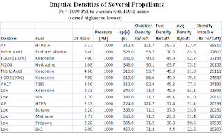 As one can see, a solid propellant like AP-HTPB-Al has one of the highest impulse densities (although in reality it will be less than listed because the core will reduce the average propellant density). Second in the table is nitric acid with furfuryl alcohol. Hydrogen peroxide with kerosene comes next. A number of denser liquid propellant combinations like N2O4-Hydrazine, Nitric Acid-Kerosene, AK27-T185 (Russian Scud missile propellant) and Lox-Kerosene follow. Liquid Oxygen and liquid hydrogen has the lowest impulse density of the propellants examined.
VISUALIZING THE RESULTS
The best way to understand the results of impulse density on rocket size is to see what different rockets with different propellants will be sized to for the same delta V performance. I will first look at upper stages and the result of impulse density on their weight and size and then look at booster stages for their comparative weights and sizes. The examination that I will do in no way considers the complications and complexities associated with making each of the propellants meet the defined requirements. It’s merely to provide a minimum number of variables so that comparisons can be made
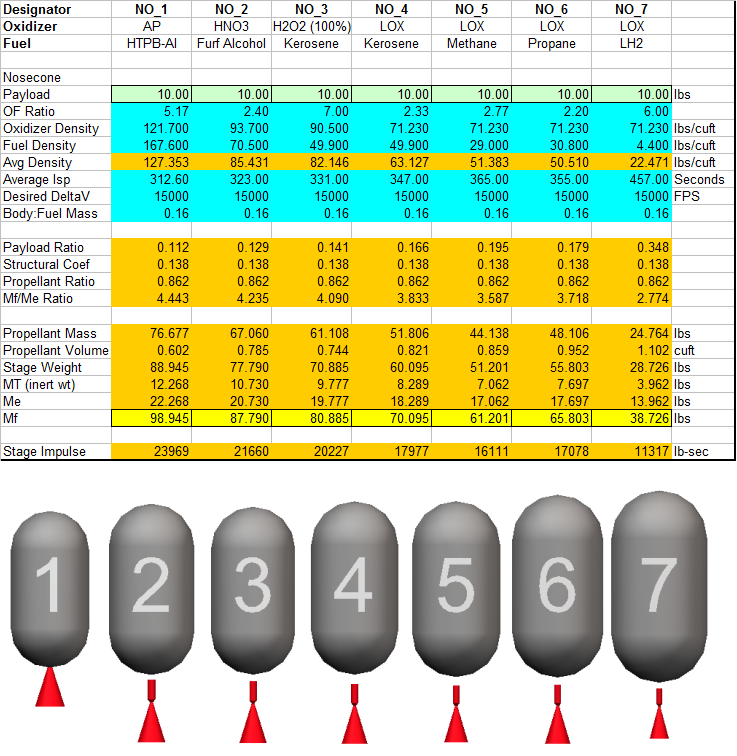
UPPER STAGES WITH DIFFERENT PROPELLANTS
First, let's examine what impact these propellant densities have on the size of an upper stage vehicle. For this exercise, let's presume that we want to have a delta V of 15000 feet per second (fps) for each of several different propellants. We'll calculate the amount of propellant required and the volume of the tanks for them. I'll show the resulting values in a table with a graphical representation of what each of the vehicles looks like.

Looking at the table of characteristics and the resultant vehicle design images, one can see that the smallest and lightest vehicle is the solid rocket motor, which also has the impulse density; the largest vehicle is Lox-Hydrogen vehicle which has the lowest impulse density. The obvious trend is that with decreasing impulse density, the upper stage vehicles get dimensionally larger (generally). Another important characteristic is that the denser propellants also result in heavier stages.
The following graph lists each of the propellants and charts their resultant Isp, weight and volume.

The obvious general trend is that decreasing the impulse density from left to right generally results in larger tank volume. In fact, the tank volume of the liquid oxygen-liquid hydrogen vehicle is almost double that of the solid propellant vehicle. Additionally, it can be seen that the weight of the stage generally decreases for the same performance as the impulse density gets smaller.
BOOSTER STAGES WITH DIFFERENT PROPELLANTS
Now let's look at the impact of density impulse on the size of booster stages. For this examination, I will take the lightest upper stage, the Lox-LH2 stage and place it into a 250 mile circular orbit. To do this, the second (upper) stage will produce the full 24161 feet per second (fps) necessary to put itself into orbit and the first (booster) stage will only be responsible for lofting its payload to altitude. I've selected this scenario because it allows me to ensure that each vehicle is subjected to nearly identical flight trajectory characteristics. This means that the only variable which will affect the vehicle will be the effects due to density impulse and its size effect on vehicles.
To do this comparison, I created a single design which is parametric with propellant volume (which is proportional to delta V). This means that the vehicle is larger or smaller depending on the amount of propellant but all other parameters scale equally (i.e. diameter to length ratio, the size of the fins relative to the body size, etc). I then calculated the size of these vehicles and simulated their flight to get to a 250 mile +/- 1 mile altitude. I adjusted the delta V to get the vehicle that met the altitude criteria. The thrust of the booster stage was the same scaled value for each: 1.333 g’s at takeoff, with compensation of the thrust for the Isp change with altitude. Now, for the solid motor, this is not the most realistic thrust profile but end burners might be able to produce something similar. Solid motors often have trouble with longer burn times and usually accelerate faster, but I needed to control the thrust to have the aerodynamic effects similar across all vehicles.

There are some obvious differences with these vehicles and their size related to their impulse density (although it could be argued that the differences are mostly superficial). The most obvious difference is design NO7 which is the Lox-LH2 propellant. Because of Lox-LH2’s performance, it requires less propellant mass to produce the same amount of delta V (in a vacuum) but its geometric size is larger. But in the atmosphere, the lower mass causes increased aerodynamic losses so the vehicle must compensate by adding more propellant. This relationship eventually balances out with a vehicle that is still physically lighter but which is substantially larger.
 One other way to look at the performance of the various propellants is to compare them by their various stage characteristics. The following table shows the length, diameter, weight and delta V for each booster propellant approach.

We seem to be able to make some generalizations from this data. Generally, the lower the impulse density, the lighter the vehicle, the more delta V is required and higher gravity and aerodynamic losses are incurred (but not necessarily drastically so) for the same overall stage performance. Again, Lox-LH2 (NO7) is an outlier in the trends.
SUMMARY
So the implications of Impulse Density generally means that a lower impulse density is a larger, lighter vehicle and vice versa. For a booster stage, higher impulse density can result in a heavier, but smaller vehicle (generally).
DEFINITION
Impulse Density relates the amount of impulse (force over time) one gets from a propellant per unit of volume. Since all propellants vary with their density from one another, it is often difficult to compare propellants' effectiveness. Impulse density allows us to make comparisons of propellants without considering their relative densities. One formula for impulse density is:
Impulse Density = Ve * d

 Where:
  Ve = exhaust velocity of propellant
  d  = density of the propellant
Remembering the relationship between Ve and Isp:
Ve = Isp * gWe see that there is a relationship between the impulse density and the specific impulse. Whereas specific impulse allows one to judge a propellant for its impulse per unit mass of propellant, Impulse Density allows one to compare propellants for their impulse per unit volume.
So another way to write the Impulse Density is:
Impulse Density = Isp * d

 where:
  Isp = propellant specific impulse
  d   = density of the propellant
The result of this form of the equation will be different from the other representation merely by a constant, g.
Understanding impulse density in a comparative manner allows us to compare different propellants for their relevant benefits in a different way from specific impulse. Essentially, there is a relationship between the impulse density of a propellant combination and the size of the vehicle to produce a certain impulse. A higher impulse density means that a smaller volume is required to contain that impulse.
COMPARATIVE IMPULSE DENSITY
The following table illustrates the impulse densities of various propellants ordered from highest impulse density towards the lowest.

VISUALIZING THE RESULTS
The best way to understand the results of impulse density on rocket size is to see what different rockets with different propellants will be sized to for the same delta V performance. I will first look at upper stages and the result of impulse density on their weight and size and then look at booster stages for their comparative weights and sizes. The examination that I will do in no way considers the complications and complexities associated with making each of the propellants meet the defined requirements. It’s merely to provide a minimum number of variables so that comparisons can be made
UPPER STAGES WITH DIFFERENT PROPELLANTS
First, let's examine what impact these propellant densities have on the size of an upper stage vehicle. For this exercise, let's presume that we want to have a delta V of 15000 feet per second (fps) for each of several different propellants. We'll calculate the amount of propellant required and the volume of the tanks for them. I'll show the resulting values in a table with a graphical representation of what each of the vehicles looks like.
Looking at the table of characteristics and the resultant vehicle design images, one can see that the smallest and lightest vehicle is the solid rocket motor, which also has the impulse density; the largest vehicle is Lox-Hydrogen vehicle which has the lowest impulse density. The obvious trend is that with decreasing impulse density, the upper stage vehicles get dimensionally larger (generally). Another important characteristic is that the denser propellants also result in heavier stages.
The following graph lists each of the propellants and charts their resultant Isp, weight and volume.

The obvious general trend is that decreasing the impulse density from left to right generally results in larger tank volume. In fact, the tank volume of the liquid oxygen-liquid hydrogen vehicle is almost double that of the solid propellant vehicle. Additionally, it can be seen that the weight of the stage generally decreases for the same performance as the impulse density gets smaller.
BOOSTER STAGES WITH DIFFERENT PROPELLANTS
Now let's look at the impact of density impulse on the size of booster stages. For this examination, I will take the lightest upper stage, the Lox-LH2 stage and place it into a 250 mile circular orbit. To do this, the second (upper) stage will produce the full 24161 feet per second (fps) necessary to put itself into orbit and the first (booster) stage will only be responsible for lofting its payload to altitude. I've selected this scenario because it allows me to ensure that each vehicle is subjected to nearly identical flight trajectory characteristics. This means that the only variable which will affect the vehicle will be the effects due to density impulse and its size effect on vehicles.
To do this comparison, I created a single design which is parametric with propellant volume (which is proportional to delta V). This means that the vehicle is larger or smaller depending on the amount of propellant but all other parameters scale equally (i.e. diameter to length ratio, the size of the fins relative to the body size, etc). I then calculated the size of these vehicles and simulated their flight to get to a 250 mile +/- 1 mile altitude. I adjusted the delta V to get the vehicle that met the altitude criteria. The thrust of the booster stage was the same scaled value for each: 1.333 g’s at takeoff, with compensation of the thrust for the Isp change with altitude. Now, for the solid motor, this is not the most realistic thrust profile but end burners might be able to produce something similar. Solid motors often have trouble with longer burn times and usually accelerate faster, but I needed to control the thrust to have the aerodynamic effects similar across all vehicles.

There are some obvious differences with these vehicles and their size related to their impulse density (although it could be argued that the differences are mostly superficial). The most obvious difference is design NO7 which is the Lox-LH2 propellant. Because of Lox-LH2’s performance, it requires less propellant mass to produce the same amount of delta V (in a vacuum) but its geometric size is larger. But in the atmosphere, the lower mass causes increased aerodynamic losses so the vehicle must compensate by adding more propellant. This relationship eventually balances out with a vehicle that is still physically lighter but which is substantially larger.


We seem to be able to make some generalizations from this data. Generally, the lower the impulse density, the lighter the vehicle, the more delta V is required and higher gravity and aerodynamic losses are incurred (but not necessarily drastically so) for the same overall stage performance. Again, Lox-LH2 (NO7) is an outlier in the trends.
SUMMARY
So the implications of Impulse Density generally means that a lower impulse density is a larger, lighter vehicle and vice versa. For a booster stage, higher impulse density can result in a heavier, but smaller vehicle (generally).
Friday, December 2, 2011
News: ESA Discovers Large Ice Deposits on Mars
Mountains and buried ice on Mars
ESA, 2 December 2011
http://www.esa.int/esaCP/SEMUGI2XFVG_index_0.html
New images from Mars Express show the Phlegra Montes mountain range, in a region where radar probing indicates large volumes of water ice are hiding below. This could be a source of water for future astronauts.
ESA, 2 December 2011
http://www.esa.int/esaCP/SEMUGI2XFVG_index_0.html
New images from Mars Express show the Phlegra Montes mountain range, in a region where radar probing indicates large volumes of water ice are hiding below. This could be a source of water for future astronauts.
Thursday, December 1, 2011
News: Best Space Pictures of 2011: Editors' Picks
Best Space Pictures of 2011: Editors' Picks
National Geographic, 1 December 2011
http://news.nationalgeographic.com/news/2011/12/pictures/111201-best-space-pictures-year-2011-aurora-eclipse-meteor-sun/
The empty payload bay of the space shuttle Endeavour is illuminated as the spacecraft zooms over city lights on Earth in May. This shot of the shuttle, at the time docked with the International Space Station, is among National Geographic News editor's picks for the best space pictures of 2011.
Wednesday, November 30, 2011
News: Shoe box-size satellites one of the next big things
Shoe box-size satellites one of the next big things
Boston Globe, 28 November 2011
http://bostonglobe.com/business/2011/11/28/shoe-box-size-satellites-one-next-big-things/mIcNPfU6V7aakZL9lYgihK/story.html
One of the next big things in space innovation is a modest cube, about the size of a coffee mug or a shoe box, now being developed to circle Earth and monitor space weather, observe the atmosphere, and test the feasibility of using a sun-powered sail to tow space junk.
Over the past decade, these diminutive cube satellites, or CubeSats,have grown in importance. Some think they are poised to have a potentially profound impact on the big-budget space industry, where missions can routinely cost hundreds of millions, similar to the effect the advent of personal computers had on computing.
Tuesday, November 29, 2011
News: Garvey Spacecraft Awarded NASA Launch Service Contract
Garvey Spacecraft, 19 October 2011
http://www.garvspace.com/2011/PR_2011_01/GSC%20press%20release%202011-01%20-%20NASA%20LSP%20contract%20award.pdf
Garvey Spacecraft Corporation (GSC) announced today that it has been awarded a contract from the NASA Launch Services Program (LSP) at Kennedy Space Center, FL to provide a high altitude launch service for demonstration NanoSatellites.
News: NASA's Nanosail-D 'Sails' Home -- Mission Complete
NASA's Nanosail-D 'Sails' Home -- Mission Complete
NASA, 29 November 2011
http://www.nasa.gov/mission_pages/smallsats/11-148.html
After spending more than 240 days "sailing" around the Earth, NASA's NanoSail-D -- a nanosatellite that deployed NASA's first-ever solar sail in low-Earth orbit -- has successfully completed its Earth orbiting mission.
Launched to space Nov. 19, 2010 as a payload on NASA's FASTSAT, a small satellite, NanoSail-D's sail deployed on Jan. 20.
The flight phase of the mission successfully demonstrated a deorbit capability that could potentially be used to bring down decommissioned satellites and space debris by re-entering and totally burning up in the Earth's atmosphere. The team continues to analyze the orbital data to determine how future satellites can use this new technology.
A main objective of the NanoSail-D mission was to demonstrate and test the deorbiting capabilities of a large low mass high surface area sail.
"The NanoSail-D mission produced a wealth of data that will be useful in understanding how these types of passive deorbit devices react to the upper atmosphere," said Joe Casas, FASTSAT project scientist at NASA's Marshall Space Flight Center in Huntsville, Ala.
Sunday, November 27, 2011
Cubesat Workshop Presentations
Cubesat Workshop Presentations
CalPoly San Luis Obispo, Various
http://mstl.atl.calpoly.edu/~bklofas/Presentations/
Presentations from various years of Cal Poly San Luis Obispo's Cubesat Workshops.
CalPoly San Luis Obispo, Various
http://mstl.atl.calpoly.edu/~bklofas/Presentations/
Presentations from various years of Cal Poly San Luis Obispo's Cubesat Workshops.
Friday, November 25, 2011
News: OpenRocket Version 1.1.9 Released
OpenRocket Version 1.1.9 Released
Open Rocket, 24 November 2011
http://openrocket.sourceforge.net/
For this version Richard Graham has implemented geodetic computation methods, which take into account the curvature of the Earth and the coriolis effect. The computation method is selected by the Geodetic calculations option in the simulation options. It's not (yet) a full spherical computation model, but should be accurate enough for almost all sub-orbital needs.
Wednesday, November 23, 2011
News: SpaceWorks Nanosat Market Study
SpaceWorks Nanosat Market Study
The Space Business Blog, 22 November 2011
http://spacebusinessblog.blogspot.com/2011/11/spaceworks-nanosat-market-study.html
SpaceWorks Commercial today released their latest nano/microsatellite market study. You can download it here. The study is quite bullish on the growth of Nanosatellites over the next decade with over 20% growth per year through 2014.
Tuesday, November 22, 2011
News: Cubesats Move Out Of The Classroom
Cubesats Move Out Of The Classroom
Aviation Week, 22 November 2011
http://www.aviationweek.com/aw/generic/story_channel.jsp?channel=space&id=news/asd/2011/11/22/08.xml&headline=Cubesats%20Move%20Out%20Of%20The%20Classroom
Cubesats — the small, cheap spacecraft popular with engineering students due to their hands-on appeal as teaching tools — are attracting attention beyond the academy as their capabilities grow and launch opportunities proliferate.
News: SpaceWorks Commercial Releases Nano/Microsatellite Launch Demand Assessment
SpaceWorks Commercial Releases Nano/Microsatellite Launch Demand Assessment 2011
SpaceWorks, 22 November 2011
http://www.sei.aero/press/press_2011-11-22.shtml
SpaceWorks Commercial (a division of SpaceWorks Enterprises, Inc.) releases a new study highlighting increasing yearly demand for orbital launch services for the nanosatellite and microsatellite market. The study, entitled “Nano/Microsatellite Launch Demand Assessment 2011” is a quantitative assessment of past launches and a projection of future launch demand up to 2020. Projections indicate more than 100 nano/micro satellites will need launches in the year 2020. A presentation summarizing this assessment is available on the SpaceWorks website.
Monday, November 21, 2011
Video: Beyond Planet Earth The Future of Space Exploration
Beyond Planet Earth: The Future of Space Exploration
American Museum of Natural History, 21 November 2011
http://www.amnh.org/exhibitions/beyond/
The Moon. Mars. An icy moon of Jupiter. A near-Earth asteroid. In the not too distant future, missions to these destinations will launch from Earth.
All would involve countless hours of planning and hard work, opportunity for scientific glory—and risk. But if the missions succeed, what adventures would unfold! Tonight, look up. Above you: the universe.
Sunday, November 20, 2011
Black Arrow: Britains Satellite Launcher
The Black Arrow was Great Britain's first indigenously-developed rocket launcher. In four flights, two were successful. It successfully put one satellite, the Prospero, into orbit, making Great Britain the sixth country to orbit a satellite (after the Soviet Union, the United States, France, Japan and China)
SOURCES
Finding accurate, authoritative information on the Black Arrow was difficult (at least in the U.S.). Therefore, one should expect a wider error margin on the weights and performances listed here. However, the values make sense with regard to various sources so they probably aren't too far off.
Because of the conflicting and non-authoritative information published widely on the Internet, I'm going to approach this discussion a bit differently. Since the Internet references conflict or give obviously wrong information, I'm going to extract some of the design information from highly authoritative sources and first principles, confirming or denying information published from less authoritative sources. Otherwise, I'll use whatever other technical information from other sources
that appears correct with the models derived from more accurate sources.
There are two primary sources that I'll base much of the analysis on. The first is the table of weights [1] published by the Royal Airforce Establishment (RAE).

The second source is a trajectory diagram [2] also published by the RAE. This diagram illustrates the time of launch events and other significant parameters of the orbital ascent.

The problem with the trajectory data diagram that warrants caution is that there is no specific identification of this trajectory with a specific vehicle (there were five of them built) as well as whether or not this diagram represents desired or actual trajectory figures. However, the results obtained by using this diagram match well with the specifications from the weight table. Therefore, I'll use at as a basis for establishing authoritative derived parameters.
GENERAL
The Black Arrow was a three stage satellite launcher able to place a 300 pound (136 kg) satellite into a 135 mile altitude Low Earth Orbit. The first and second stages used liquid propellants and the third stage used a solid motor.
The following table shows the performances and weights of the stages and its constituent components. Because the second stage carried and then jettisoned the payload aerodynamic fairing during flight, it has been broken into two stages, BA2A and BA2B (for before and after fairing separation, respectively):

DETERMINING ACTUAL STAGE SPECIFIC IMPULSES
Most sources, even from the 1960's say that the Specific Impulse (Isp) is 265 seconds for both the first stage and the second stage. This is obviously wrong for several reasons because the first stage flies through a varying atmospheric pressure regime throughout its flight and therefore the Isp will vary. We need to know what the range of Isp variance is to properly model the vehicle. Additionally, although the first and second stage motors were very similar, there were significant differences that affected their performances. Specifically, although the second stage may have used the same motor chambers as the first stage, it has been stated in numerous sources that the second stage had a nozzle extension. This would make the Isp of the second stage different from that of the first. Therefore, I need to look at what realistic Specific Impulses might be for each of the stages.
There is authoritative information that might give clues to the likely performances of the first and second stage motors. Using the two primary sources, I can derive some bounds on the specific impulses of the engines in each stage.
For review, the formula for Isp (Specific Impulse) is:
Isp = Thrust * time / weightWhere the Isp (in seconds) is equal to the thrust (in force) times the number of seconds of that thrust divided by the weight of the propellant (also in force units) required to produce the thrust. Since you have force units over force units in the equation, they cancel out, leaving only seconds as the remaining unit.
The weight table says that the propellant weight of the first stage is 28735 lbs with a thrust of 50000 lb-f at sea level and 57640 lb-f in vacuum. The trajectory diagram says that the first stage burn duration was 131.2 seconds. The propellant weight of 28735 lbs divided by 131.2 seconds means that (on average), the propellant usage rate is 219.017 lbs/sec. Now, I have no idea whether or not the engines were throttled during the flight so it is possible that this only does represent an average usage, and not an actual per-second usage, but it's the best information I have. Based on these numbers and the Isp equation, we can establish that the effective Sea Level Isp is:
 Eff. Isp(SL) = 50,000 lb-f * 1 s / 219.017 lb-m
 Eff. Isp(SL) = 228.293 seconds

 Eff. Isp(VAC) = 57640 lb-f * 1 s / 219.017 lb-m
 Eff. Isp(VAC) = 263.176 seconds
The Weight table lists the second stage as having 6522 lbs of propellant and a vacuum thrust of 15340 lb-f. The trajectory diagram shows the burn time of the second stage as 116 seconds. With 6522 lbs of propellant burnt in 116 seconds, the average propellant usage is 56.224 lb-m/s. Using the Isp equation, we can specify the effective Isp as:
 Eff. Isp(VAC) = 15340 lb-f * 1 s / 56.224 lb-m
 Eff. Isp(VAC) = 272.84 seconds
These answers make a basic kind of sense because the first stage motor's Isp will vary throughout flight up to its maximum Isp performance in a vacuum. The second stage, having a nozzle extension, will have somewhat greater Isp in vacuum.
For the third stage, I could find no authoritative source for the motor efficiency; I used an Isp value which is widely cited on the Internet. The propellant weight values I used are derived from [5].
Whether these estimations are accurate representations of the actual usage or not, I can't say. But, a rocket which has these parameters would closely meet the basic performance characteristics specified in the reference documents.
FIRST STAGE
The first stage utilized a Gamma-8 type rocket motor which burned 90% Hydrogen Peroxide and Kerosene. The Gamma 8 consisted of 8 separate chambers in a cruciform shape which gimballed on one axis each. These were fed through a peroxide-driven turbopump which raised the chamber pressure to about 640 PSI (reported as 44 bar/638 PSI in several sources but as high as 47.4 bar/687 PSI in other sources). Each chamber had an expansion ratio of about 10 giving them good high altitude performance: a Sea Level Isp of about 228 seconds and a vacuum Isp of about 265 seconds.
Regarding the Gamma-8 motors, various sources say that they had expansion ratios anywhere from 60 to 80. However, no motor running at sea level will have stable exhaust if the exit exhaust pressure is below about 40% of the atmospheric pressure. With a chamber pressure of 640 PSI, the exhaust pressure of a 60:1 nozzle will be about 1 PSI versus the 14.7 PSI atmospheric pressure. Sixty-to-one or greater appears to be too high of an expansion ratio for the first stage motors. Historical sources tell us that the Gamma-8 motor chambers were derived from the Gamma 301. A cross sectional diagram of the Gamma 301 is available in [4]:
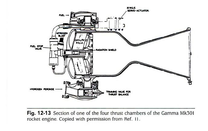
Measuring the Gamma-301 ratio of the diameters (squared) of the nozzle exit versus the throat shown in this picture gives an area ratio of 10.27. All pictures of the first stage motors appear to have this ratio in all pictures that I've seen. Therefore, I reject the various claims that the first stage motors had an expansion ratio of 60, 80 or more. The expansion ratio appears to be about 10 which is consistent with exhaust stability theory, the computed Isp's and various images of the motors.

If I model the motors using a combustion analysis program with the published values, then I get the following results:

These values very closely match the values derived by using the flow rates and thrusts. So, if the motors ran closer to 100% efficiency and the turbopumps used about 6% of the calculated efficiency to operate, then we would see the kinds of Isp values that I've calculated.
SECOND STAGE
The second stage used two of the same chambers that made up the 8 motors of the Gamma-8. A nozzle extension was added to the motors to give a reported expansion ratio of 350:1 (according to some sources). These motors are reported as having a vacuum Isp of 265 seconds but my analysis shows it's likely closer to 273 seconds.
The second stage carried the payload fairing. The trajectory table shows the payload fairing being ejected after 180 seconds. The weight of the fairing can be found in the weight table[1].
For the second stage motor, there does not appear to be any authoritative source referencing the expansion ratio of the nozzle. But using the 94% combustion efficiency derived for the first stage, and the derived value of the vacuum Isp as being 272.84 seconds, then the motor maximum theoretical Isp would have to be something like 272.84 s / 0.94 or 290.26 seconds. Again using a combustion analysis software, and the pressure and mixture ratios used in the first stage motors, we can estimate that the second stage expansion ratio had to be at least 16:1 as the minimum necessary expansion ratio. The various pictures of the second stage nozzles seem to suggest that the nozzle expansion ratio may have been closer to 60 or 80. Maybe this was the value that was wrongly attributed to the first stage expansion ratio in the various sources. As it stands, I have no idea what the accurate expansion ratio was.
THIRD STAGE
The third stage used a solid propellant rocket motor (called Waxwing) without guidance but which was spun to be gyroscopically stabilized. Again, sparse authoritative information exists for its specifications.
GUIDANCE AND CONTROL
Like the few rockets we have looked at so far, the guidance system was kept in the second stage, and the third stage was unguided. Using the familiar "point and fire" technique, the second stage would orient itself to the desired angle for the orbit, small rockets were used to spin up the third stage to ensure orientation stability and then the third stage would fire its motor.
The first stage control system utilized motor gimbaling to provide full yaw-pitch-roll control. The second stage also utilized gimbaling of two motors to provide full control during motor firing. After the second stage propellant was burned out, the second stage used a pressurized nitrogen cold-gas reaction control system to orient the third stage for firing.
AERODYNAMIC AND GRAVITATIONAL LOSSES
Simulations using the specifications above result in an observed first stage aerodynamic loss of 587 feet per second (fps) and gravitational losses of about 4218 fps. The reason for these kinds of losses are due to the Black Arrow's relatively large diameter relative to its length (it had a fineness ratio of 7) and its relatively low acceleration (takeoff thrust was only 25% more than GLOW).
SUMMARY
I can't say how accurate these results are, but they fit and describe the vehicle fairly well. A vehicle with the specifications described above would have similar performance to those described in the various sources. Nonetheless, the derived specifications are still useful metrics for comparison against other vehicles.
REFERENCES
[1] Weight Table, derived from reference [3] page 28.
[2] Trajectory Table, derived from reference [3] page 50.
[3] The Black Arrow rocket: a history of a satellite launch vehicle and its engines
    Millard Douglas, 2001, ISBN 1900747413
[4] History of Liquid Propellant Rocket Engines
    Sutton George Paul, 2006, ISBN 1563476495
[5] A Vertical Empire
    Hill C.N., 2001, ISBN 1-86094-267-9
Friday, November 18, 2011
Video: Team Phoenicia Nanosat Launcher Challenge Seminar
Nanosat Launcher Challenge Seminar: Team Phoenicia as a Supplier and How to Get Sponsorships
YouTube, 15 November 2011
http://www.youtube.com/user/teamphoenicia#p/a/u/0/ijXuEK8VwPI
William Baird Team, Leader of Team Phoenicia, presents on how Team Phoenicia contracts out (first part of the talk) and how to get sponsorships (second part).
YouTube, 15 November 2011
http://www.youtube.com/user/teamphoenicia#p/a/u/0/ijXuEK8VwPI
William Baird Team, Leader of Team Phoenicia, presents on how Team Phoenicia contracts out (first part of the talk) and how to get sponsorships (second part).
Video: Hand Made Mini V12 Engine
Hand Made Mini V12 Engine
LiveLeak, 18 November 2011
http://www.liveleak.com/view?i=fd8_1321653527
Not rockets, but very neat...
Very detailed V12 motor. This video shows some of the manufacturing and some of the assembly.
LiveLeak, 18 November 2011
http://www.liveleak.com/view?i=fd8_1321653527
Not rockets, but very neat...
Very detailed V12 motor. This video shows some of the manufacturing and some of the assembly.
News: Blue Origin spruces up rocket report
Blue Origin spruces up rocket report
Cosmic Log, 18 November 2011
http://cosmiclog.msnbc.msn.com/_news/2011/11/18/8871807-blue-origin-spruces-up-rocket-report
Blue Origin, the secretive rocket venture founded by Amazon.com billionaire Jeff Bezos, has unveiled a spruced-up website that includes videos of its successful "short hop" flight test back in May.
News: Rocket Racing League backs off Melbourne plan
Rocket Racing League backs off Melbourne plan
Florida Today, 17 November 2011
http://www.floridatoday.com/article/20111118/NEWS01/311180024/Rocket-Racing-League-backs-off-Melbourne-plan
The fledgling Rocket Racing League is no longer considering moving its headquarters from Orlando to Melbourne International Airport, said Mike D’Angelo, chief operating officer.
Tuesday, November 15, 2011
News: US student to fill heavens with Sprites
US student to fill heavens with Sprites
The Register, 15 November 2011
http://www.theregister.co.uk/2011/11/15/sprite_project/
A Cornell University postgrad student is offering enthusiasts the chance to get their own diminutive bit of kit into space, in the form of a miniature satellite.
Zac Manchester's Sprite is a solar-powered board "about the size of a couple of postage stamps", which packs a "microcontroller and a radio for communicating with ground stations from low Earth orbit".
News: XCor Contest for a Lynx Suborbital Flight
XCOR NSRC-2012 Research/Education Flight Prize
XCor, 15 November 2011
http://www.xcor.com/NSRC-2012-contest-rules/
Open to Earlybird Professional, Advanced Professional, or Advanced Student Paid Registration (Onsite and One-Day Registrations are not eligible) prior to 0830AM PT 26 February 2012 of the Next-Generation Suborbital Researchers Conference 2012 (NSRC-2012) who are: legal residents of countries not on the US State Department’s Country Policies and Embargoes List and where this contest is deemed legal by the governmental authorities, 18 years of age or older as of date of registration, a paid registrant at NSRC-2012, and satisfy other qualifications as found in the Official Rules and any XCOR or government rules, laws or regulations required to fly an experiment on the Lynx Mark I suborbital spacecraft.
News: UK Space Agency OKs teeny-tiny satellite
UK Space Agency OKs teeny-tiny satellite
The Register, 8 November 2011
http://www.theregister.co.uk/2011/11/08/ukube_1_design_approved/
"The UK Space Agency has approved the design of UKube-1, the UK's first CubeSat mission.
Last week, a team of engineers from Clyde Space, a microspacecraft maker, submitted their design for the UKube-1 to be reviewed by a team of experts, who concluded that the design was sound."
Thursday, November 10, 2011
The Scout Launch Vehicle
The Scout was an all solid rocket motor launch vehicle. It was one of the smallest and earliest launchers developed by NASA, used for payloads less than about 550 lbs into low Earth orbit (LEO). Its development began in 1957 and its first test launch was in 1960, just 2 years after the US launched the Explorer satellite. The first Scout successfully placed a payload into orbit in 1961. The Scout family of rockets had a long lifespan of over 30 years with 118 launches and the last one being launched in 1994.

There's a lot of information on the Scout launch vehicle available on the web, and there were many different variants over the years with payload capabilities from a few pounds up to 550 pounds. I will only concentrate on aspects relevant to the discussion of developing small launchers.
GENERAL
The Scout was a four stage all-solid propellant vehicle (except that liquids were used for orientation control of the upper stages). The first stage was an Algol motor which used aerodynamic fins and jet vanes in the rocket motor exhaust stream for control. The second stage was a Castor motor which used hydrogen peroxide reaction control rockets for guidance and orientation. The third stage was an Antares motor which also used hydrogen peroxide reaction control rockets for orientation. The fourth stage used an Altair motor which was unquided but spun on its long axis for orientation stability.

GUIDANCE AND CONTROL
It is worth focusing on the guidance and control approach used on the Scout vehicles since it has lessons for those designing small launch vehicles. First, the guidance and control system of the Scouts was a relatively simple pitch rate system controlled by a timer. The roll and yaw axes used a gyro system to ensure that the vehicle maintained a specific roll and yaw attitude throughout its flight. This reduced the guidance problem from three rotational orientation dimensions down to a one-dimensional pitch over problem. Clockwork mechanisms used pre-programmed pitch rates to ensure that the vehicle had the proper pitch throughout the flight to orbit. At the end of the third stage flight, spin rocket motors spun up the fourth stage to provide it some amount of orientation stability. Then the fourth stage motor was ignited to add the last amount of delta V required to get the payload to orbit. Like other small launchers, the final stage was unguided and the lower stages were responsible for orienting it before firing.
MASS CONSIDERATIONS
We can also learn something by considering the side effects necessary to take a raw motor and turn it into a useful stage. For the following analysis, I will consider the Scout D configuration.
The first stage of the Scout D used a Algol III motor. In its basic configuration, the motor weighs 31305.10 pounds and has a total propellant weight of 28,059.77 pounds. Subtracting the propellant from the total weight leaves an inert weight of about 3245.33 pounds. This results in an inert:propellant ratio of 0.116. However, if we look at the stage weights of the first stage, we see that its inert weight is 4211.37 pounds. Therefore, the control system (which includes fins, jet vanes and other hardware) adds about 966.04 pounds resulting in a stage inert:propellant ratio of 0.1489. So, the inert weight increased from 3245.33 lbs to 4211.37 lbs for a weight increase of 130 % (30% more weight for the control system).
The second stage of the Scout D used a Castor IIA motor. In its basic configuration, the motor weighs 9774.26 pounds and has a total propellant weight of 8206.15 pounds. Subtracting the propellant from the total weight leaves an inert weight of about 1568.11 pounds. This results in an inert:propellant ratio of 0.1911. Looking at the full second stage weight, however, we see that the stage inert weight is 2399.06 pounds. Therefore, the control system and staging mechanisms of this stage weighs about 831.49 lbs resulting in a stage inert:propellant ratio of 0.2891. So, the inert weight increased from 1568.11 to
2399.06 lbs for a weight increase of 153 % (50% more weight for control and staging systems).
The third stage of the Scout D used an Antares II motor. In its basic configuration, the motor weighs 2796.80 pounds and has a total propellant weight of 2559.43 pounds. Subtracting the propellant from the total weight leaves an inert weight of about 237.37 pounds. This results in an inert:propellant ratio of 0.0927. Looking at the stage weight, though, we see that the stage inert weight is 771.95 pounds. Therefore, the control system and staging mechanisms added about 534.58 pounds with a resulting stage inert ratio of 0.2982. The staging and control system added 534.48 lbs to the motor's 237.37 lbs and thus added 225 percent (or 125 percent increase) to this stage.
The fourth and final stage of the Scout D used an Altair III motor which weighs 666.63 pounds full and has 607.15 pounds of propellant; the inert weight is thus 59.48 pounds for an inert:propellant ratio of 0.0980. The third stage inert weight is 104.62 lbs, 45.14 lbs worth of staging mechanism (since there is no control system). This is an increase of 176% (or 76% increase) just for staging mechanisms.
Although this section might seem like just a bunch of useless weight breakdowns and percentages, it is sometimes good to know these percentages to provide a grounded estimate of control system weight increase. One trend that might be noticed is that as we go up the stages, the mass of the control and staging mechanisms become a higher percentage of the stage weight. This is because it's not always easy to scale these down equally with the stages. This issue is especially significant for smaller launch vehicles.
AERODYNAMIC AND GRAVITY LOSSES
Just to be complete and provide some basis for comparison, I will give my estimate of the aerodynamic and gravity losses.
Because the Scout had a high fineness ratio (length to diameter ratio) of about 20, it had relatively low aerodynamic losses. Of course, the trajectory and other factors affect the overall aerodynamic losses and gravity losses, but using a simulation close to that of the Scout 185C, my simulations show that the aerodynamic losses were about 327.76 fps and gravity losses were about 2640.40 fps for the first stage.
LESSONS THAT ONE MIGHT LEARN
There are three major lessons that I think are worth learning from the Scout family of rocket launchers. First, it is possible to have an orbital rocket launcher which uses only simple one-degree pitch control guidance (once the other two axes are stabilized). Second, it is possible to have no guidance in the final stage. Third, it is possible to have orbital rockets with length to diameter ratios of 20 or more at lift-off. These facts provide some credibility for smaller orbital rocket designs that might also utilize these design techniques.
REFERENCES
Scout: The Unsung Hero of Space
YouTube http://www.youtube.com/watch?v=btRk6AhoOmI
Scout Launch Vehicle Program, Part 2, Phase 6 Final Report
NASA, 19820073029_1982073029.pdf
Project Development Plan: Scout Program
NASA, 19810069924_19810069924.pdf
News: Space Shuttle's Last Satellite Gets Hobby Rocket Boost
Space Shuttle's Last Satellite Gets Hobby Rocket Boost
Rocketry Planet, 7 November 2011
http://www.rocketryplanet.com/index.php?option=com_content&task=view&id=3706&Itemid=30#axzz1dGeK2tPX
"To ensure mission longevity, four small thrusters were included on the spacecraft, each using the propellant grain and nozzle assembly from an Aerotech E28T rocket motor. On November 4th, the first of these motors was fired to raise the orbit and increase the mission duration."
Sunday, November 6, 2011
News: Launch Magazine Online
Launch Magazines Online
Launch, 6 November 2011
http://www.launchmagonline.com/
Several back issues of Launch magazine are available online at the website. From the webpage:
"LAUNCH Magazine was created in 2006 to celebrate spaceflight and the hobbies inspired by it. The magazine was published from September 2006 through December 2008. It included interviews with current and former astronauts, scientists and visionaries in all aspects of spaceflight and aerospace. The issues also included a wide range of hobby rocketry articles, including coverage of major national competitions as well as model construction techniques, and historically-important interviews with pioneers of the hobby."
News: Small Satellites Prompt Big Ideas for Next 25 Years
Small Satellites Prompt Big Ideas for Next 25 Years
Space.com, 17 October 2011
http://www.space.com/13283-small-satellites-cubesats-research-technology.html
Call them a powerful force in the universe. Smallsats have already shown their ability to monitor disasters, study Earth’s environment and support agriculture, cartography and earth science missions.
Thursday, November 3, 2011
Moon 2.0: A Beautiful Launch Simulator
Moon 2.0
http://code.google.com/p/moon-20/downloads/list
Check out the Moon 2.0 launch simulator. It's a beautiful program to simulate a launch vehicle. Because it's open source, you can adapt it to just about any need.
I have been playing with it with known performance simulations, but have yet to have it generate accurate trajectories. However, as I study this program, I see it is possible to add custom data files and I'll be experimenting with trying to get accurate trajectories from various designs.
Tuesday, November 1, 2011
News: Nanosat Challenge Allied Organization Selected
NASA And Space Florida Small Satellite Research Center Partner In Space Launch Challenge
NASA, 1 November 2011
http://www.nasa.gov/home/hqnews/2011/nov/HQ_11-370.html
NASA has signed an agreement with the Space Florida Small Satellite Research Center of Cape Canaveral, Florida, to manage the Nano-Satellite Launch Challenge, one of the agency's new Centennial Challenges prize competitions.
The Nano-Satellite Launch Challenge is to launch satellites with a mass of at least 2.2 pounds (1 kg) into Earth orbit, twice within the span of one week. The new challenge has a NASA-provided prize purse of $2 million.
The objective of the competition is to encourage innovations in propulsion and other technologies, as well as operations and management relevant to safe, low-cost, small payload delivery system for frequent access to Earth orbit. Innovations stemming from this challenge will be beneficial to broader applications in future launch systems. They may enhance commercial capability for dedicated launches of small satellites at a cost comparable to secondary payload launches -- a potential new market with government, commercial, and academic customers.
News: Cube-Sats - small satellites for the common man
Cube-Sats - small satellites for the common man
Las Crucas Sun-News, 31 October 2011
http://www.lcsun-news.com/las_cruces-news/ci_19237059
"Here is a great accomplishment: Montana State University, Auburn, Utah State and Michigan State launched Cube-Sat satellites on Oct. 28 at 5:30 a.m. You can watch the launch at www.cubesat.org. The satellites are launched in the same launcher, called a P-POD (Poly Picosatellite Orbital Deployer). The Cube-Sats are 10x10x10 cm in size."
Sunday, October 30, 2011
The Vanguard Satellite Launch Vehicle
So much has been written about the Vanguard launchers that research on them
was pretty easy. Nonetheless, it is worth putting the stage information in
a format that can make comparisons easier with other similar launchers.
However, it looks like we can safely say that the Vanguard is the second
smallest land-based launcher (by mass).
In summary, the Vanguard was a small three stage rocket launcher able to
place 22 lbs payloads into orbit. The first stage used liquid oxygen (LOX)
with kerosene as the fuel. The second stage used nitric acid with UDMH
as the fuel. The third stage was a solid rocket motor without guidance.
The second stage was responsible for orienting the third stage prior to
its ignition to ensure a proper orbit. As the Engineering Summary document
states:
like the Lambda 4S is that it has substantially lower mass ratios. Even
though the Vanguard is only a 3 stage vehicle, doesn't have substantially
higher Isp, it outperforms the Lambda 4S in delta V despite a larger effective payload.
THE STATISTICS
Here's the statistics table for Vanguard SLV-1. The SLV-1 was preceded by
six test vehicles, TV-0 through TV-5, and was the first operational version
of the design series. Later versions had numerous improvements over this
basic design. Although SLV-1 failed to place a payload in orbit, it represents
the basic Vanguard design and is the one that I used for my analysis. The
reason for SLV-1's failure likely was a control system problem which resulted
in stage 3 having an improper trajectory.

It should be pointed out that the calculated Gross Liftoff Weight (GLOW) is
different than that in the Engineering Summary document. This is because
they use a weight which includes ice on the Lox tank and aerodynamic
surfaces used on the ground to minimize wind shaking of the vehicle.
Therefore, the GLOW used in the analysis subtracts out the ice and
aerodynamic wind breaks.
One other significant issue is that the nosecone is properly part of stage 2
but its weight is included in stage 1. The reason for this is that the nose cone
is ejected from stage 2 shortly after separation and therefore, its effects
are not felt by stage 2 but mostly by stage 1.
STAGE 1
Although the Engineering Summary document is authoritative, making sense
of the effects of various weights on stage 1 requires careful attribution
of various weights to the overall stage performance. In the Rocket Equation,
it is important to get the weight at liftoff (GLOW) and the weight at stage
burn out correct as well as the effective specific impulse (Isp). These weights
have to be factored properly into the analysis or the results will not be
as accurate as one might desire.
In the case of stage 1, it is necessary to figure in the weights of the
Hydrogen Peroxide and the Helium used in the propulsion system and account
for their effect on both the weight and the effective propulsion system
efficiency as expressed by the average Isp. This means that the weights
of these fluids must be included into the weight of the "propellants"
which includes the oxidizer and the fuel. Doing so, gives the stage
weights below:
as 340 lbs, but only 315 lbs is reported as having been used. Therefore,
the additional 25 lbs was assigned to the burnout weight of stage 1.
to 616 PSI. The exhaust gas of the turbopump was directed to roll control
nozzles to provide attitude control beyond the stage 1 motor gimballing.
STAGE 2
Stage 2 used pressure fed nitric acid and Unsymmetrical DiMethyl Hydrazine (UDMH)
as propellants. The motor used was an Aerojet AJ10-37. The AJ10 motor, with
improvements, has continued to be used to this day in the Delta II upper stage.
With variations, this motor has also been used on the Apollo Service Module and
on the Shuttle's Orbital Maneuvering System. This motor has a long history from
the first American orbital attempts to this day.
One surprising aspect of stage 2 is its use of liquified propane as the attitude
control gas for roll control. A blanket heater was used to keep the propane
vapor pressure at 240 PSI. Again, the propane's weight has to be taken into
account for the stage performance
Stage three used a solid rocket motor which was spun along its axis to
maintain orientation. The second stage essentially used "point and
shoot" with the third stage and it contained the guidance system.
A spring-loaded separation device separated the payload from the third
stage motor at the appropriate time.

PERFORMANCE SUMMARY
Based on the vehicle defined in the performance table, above, an
aerodynamic model and an Isp vs altitude model, a simulation was
performed to identify various performance characteristics. The
trajectory was made to match the published values in the Engineering
Summary. From this, we can estimate gravity and aerodynamic losses
of the first stage.
to each stage:
The Vanguard satellite launcher provides an interesting example for those
interested in small launch vehicles. The idea of a small launch vehicle
with an unguided final stage provides one way to simplify the design
and development task. It drops the weight of the guidance system from
the final stage where it will have the greatest impact on launch vehicle
weight, down to the second stage where it will have less effect.
The Vanguard satellite launch vehicle is a fascinating example of a
small orbital launcher.
REFERENCE
The Vanguard Satellite Launching Vehicle - An Engineering Summary
http://hdl.handle.net/2060/19740072500
was pretty easy. Nonetheless, it is worth putting the stage information in
a format that can make comparisons easier with other similar launchers.
However, it looks like we can safely say that the Vanguard is the second
smallest land-based launcher (by mass).
In summary, the Vanguard was a small three stage rocket launcher able to
place 22 lbs payloads into orbit. The first stage used liquid oxygen (LOX)
with kerosene as the fuel. The second stage used nitric acid with UDMH
as the fuel. The third stage was a solid rocket motor without guidance.
The second stage was responsible for orienting the third stage prior to
its ignition to ensure a proper orbit. As the Engineering Summary document
states:
    "A three stage vehicle, with two guided stages and an
    unguided but spin-stabilized third stage, fired at
    second stage apogee, represented the most efficient
    vehicle combination consistent with rocket technology
    at that time."
One of the most obvious things about the Vanguard versus a solid launcherlike the Lambda 4S is that it has substantially lower mass ratios. Even
though the Vanguard is only a 3 stage vehicle, doesn't have substantially
higher Isp, it outperforms the Lambda 4S in delta V despite a larger effective payload.
THE STATISTICS
Here's the statistics table for Vanguard SLV-1. The SLV-1 was preceded by
six test vehicles, TV-0 through TV-5, and was the first operational version
of the design series. Later versions had numerous improvements over this
basic design. Although SLV-1 failed to place a payload in orbit, it represents
the basic Vanguard design and is the one that I used for my analysis. The
reason for SLV-1's failure likely was a control system problem which resulted
in stage 3 having an improper trajectory.

It should be pointed out that the calculated Gross Liftoff Weight (GLOW) is
different than that in the Engineering Summary document. This is because
they use a weight which includes ice on the Lox tank and aerodynamic
surfaces used on the ground to minimize wind shaking of the vehicle.
Therefore, the GLOW used in the analysis subtracts out the ice and
aerodynamic wind breaks.
One other significant issue is that the nosecone is properly part of stage 2
but its weight is included in stage 1. The reason for this is that the nose cone
is ejected from stage 2 shortly after separation and therefore, its effects
are not felt by stage 2 but mostly by stage 1.
STAGE 1
Although the Engineering Summary document is authoritative, making sense
of the effects of various weights on stage 1 requires careful attribution
of various weights to the overall stage performance. In the Rocket Equation,
it is important to get the weight at liftoff (GLOW) and the weight at stage
burn out correct as well as the effective specific impulse (Isp). These weights
have to be factored properly into the analysis or the results will not be
as accurate as one might desire.
In the case of stage 1, it is necessary to figure in the weights of the
Hydrogen Peroxide and the Helium used in the propulsion system and account
for their effect on both the weight and the effective propulsion system
efficiency as expressed by the average Isp. This means that the weights
of these fluids must be included into the weight of the "propellants"
which includes the oxidizer and the fuel. Doing so, gives the stage
weights below:
Fuel and Oxidizer:      15952 lbs
Helium:                    13 lbs
Hydrogen Peroxide:        315 lbs
---------------------------------
Propellant Weight:      16280 lbs
It should be noted that the total Hydrogen Peroxide weight was given
as 340 lbs, but only 315 lbs is reported as having been used. Therefore,
the additional 25 lbs was assigned to the burnout weight of stage 1.
Reported Emtpy Wt:       1587 lbs
Unused Peroxide:           25 lbs
---------------------------------
Burnout Weight:          1612 lbs
The first stage engine used a turbopump to raise the propellant feed pressure
to 616 PSI. The exhaust gas of the turbopump was directed to roll control
nozzles to provide attitude control beyond the stage 1 motor gimballing.
STAGE 2
Stage 2 used pressure fed nitric acid and Unsymmetrical DiMethyl Hydrazine (UDMH)
as propellants. The motor used was an Aerojet AJ10-37. The AJ10 motor, with
improvements, has continued to be used to this day in the Delta II upper stage.
With variations, this motor has also been used on the Apollo Service Module and
on the Shuttle's Orbital Maneuvering System. This motor has a long history from
the first American orbital attempts to this day.
One surprising aspect of stage 2 is its use of liquified propane as the attitude
control gas for roll control. A blanket heater was used to keep the propane
vapor pressure at 240 PSI. Again, the propane's weight has to be taken into
account for the stage performance
Fuel and Oxidizer:      3372 lbs
Propane:                  13 lbs
Helium:                   17 lbs
--------------------------------
Propellant Weight:      3402 lbs
STAGE 3
Stage three used a solid rocket motor which was spun along its axis to
maintain orientation. The second stage essentially used "point and
shoot" with the third stage and it contained the guidance system.
A spring-loaded separation device separated the payload from the third
stage motor at the appropriate time.

PERFORMANCE SUMMARY
Based on the vehicle defined in the performance table, above, an
aerodynamic model and an Isp vs altitude model, a simulation was
performed to identify various performance characteristics. The
trajectory was made to match the published values in the Engineering
Summary. From this, we can estimate gravity and aerodynamic losses
of the first stage.
Designed delta V:       10594.742 fps
Observed delta V:        6399.13  fps
Aerodynamic Losses:       440.31  fps
Gravity Loss:            3755.302 fps
Additionally, we can observe the apparent allocation of delta velocity (delta V)
to each stage:
Stage 3:                14072.890 fps
Stage 2:                10410.299 fps
Stage 1:                10594.742 fps
-------------------------------------
Total:                  35077.931 fps
SUMMARY
The Vanguard satellite launcher provides an interesting example for those
interested in small launch vehicles. The idea of a small launch vehicle
with an unguided final stage provides one way to simplify the design
and development task. It drops the weight of the guidance system from
the final stage where it will have the greatest impact on launch vehicle
weight, down to the second stage where it will have less effect.
The Vanguard satellite launch vehicle is a fascinating example of a
small orbital launcher.
REFERENCE
The Vanguard Satellite Launching Vehicle - An Engineering Summary
http://hdl.handle.net/2060/19740072500
Friday, October 28, 2011
News: NASA Robotic Lander Test Flight Nov. 4
NASA Robotic Lander Test Flight Nov. 4
SpaceRef, 28 October 2011
http://www.spaceref.com/news/viewpr.html?pid=35088
NASA will conduct a 100-foot robotic lander altitude test flight Friday, Nov. 4, to mature the technology needed to develop a new generation of small, smart, versatile robotic landers capable of achieving scientific and exploration goals on the surface of the moon, asteroids or other airless bodies.
Thursday, October 27, 2011
Reports on Wiki-Launcher
Here are various reports by various people working on ideas related to the
N-Prize [http://www.n-prize.com/]. There might be something of interest
for you in these.
Study of a nozzle vector control for a low cost mini-launcher
http://upcommons.upc.edu/pfc/bitstream/2099.1/12521/1/memoria.pdf
Study and Implementation of the stability and control system of a mini-launcher
http://upcommons.upc.edu/pfc/bitstream/2099.1/12940/1/memoria.pdf
Design and Implementation of a Second Stage Nozzle for a Low Cost Mini-Launcher
http://upcommons.upc.edu/pfc/bitstream/2099.1/11742/1/memoria.pdf
Implementation of a femto-satellite and a mini-launcher
http://upcommons.upc.edu/pfc/bitstream/2099.1/9652/1/memoria.pdf
Use of Hardware-on-the-loop to test missions for a low cost mini-launcher
http://upcommons.upc.edu/pfc/bitstream/2099.1/11754/7/TFC_LaiaNavarro_memoria_v2.0.pdf
Design and Implementation of a Synthetic Aperture Antenna for a Femto-Satellite
https://upcommons.upc.edu/pfc/bitstream/2099.1/11686/1/memoria.pdf
Study of a Low Cost Inertial Platform for a Femto-Satellite Deployed by a Mini-Launcher
http://upcommons.upc.edu/pfc/bitstream/2099.1/9668/7/TFC_EsteveBardolet_memoria_V2.pdf
There's also a bit more information here:
Wikilauncher
Google Code
http://code.google.com/p/moon-20/wiki/WikiLauncher
Wednesday, October 26, 2011
News: Generation Orbit Vies for Small Satellite Air Launch
Generation Orbit Vies for Small Satellite Air Launch
Generation Orbit, 26 October 2011
http://www.generationorbit.com/
Generation Orbit Launch Services, Inc. (or GO) presents a fast, flexible, and dedicated nanosatellite (1-30 kg) orbital payload delivery service called GO Launcher, utilizing existing high speed jet aircraft and mostly existing rockets.
GO1 = 1 to 10 kg to Low Earth Orbit
GO1 would be an initial demonstrator utilizing mostly existing solid rockets, essentially a minimum viable launch system. GO1 could mature into an operational capability in the 1-10 kg class (LEO payload delivery capability, 250 km circular orbit). The GO1 system may include international participation.
GO2 = 20 to 30 kg to Low Earth Orbit
GO2 would be a larger operational system than GO1 that offers a minimum payload delivery service in the 20-30 kg class (LEO payload delivery capability, 450 km circular orbit) with the potential for future growth. GO2 would use the experience gained from GO1 to reduce overall risk and prove the "Your Orbit, On Time" operations model. GO2 would also include options for inclusion of new technologies.
Tuesday, October 25, 2011
News: Rumor of Nanosat Challenge Allied Partner
Rumor of Nanosat Challenge Allied Partner
Team Phoenicia, 24 October 2011
http://teamphoenicia.blogspot.com/2011/10/regarding-team-phoeniciatechshop.html
"Delightfully, we were just updated that the agreement has been signed between NASA and the allied org. HOWEVER! We were told to hang on for the official PR mill to get set to grind. This was not NASA's choice, fwiw. They want to get this out as fast as possible, too. They have been directed to hold off as well."
News: Welcome to Copenhagen Suborbitals
Welcome to Copenhagen Suborbitals
Wired, 24 October 2011
http://www.wired.com/wiredscience/2011/10/welcome-to-copenhagen-suborbitals/
"We design and build everything from scratch using ordinary materials. We try to overcome the complex process of making a suborbital space rocket by letting the ordinary and plain be our guide, instead of letting the complex and extreme become our obstacles."
Monday, October 24, 2011
News: Replicators Have Arrived
Replicators Have Arrived
The Once and Future Moon, 24 October 2011
http://blogs.airspacemag.com/moon/2011/10/replicators-have-arrived/
"We’re not quite there yet but crude versions of such imagined machines already exist. These machines are called “rapid prototype” generators or three-dimensional printers. They take digitized information about the dimensions and shape of an object and use that data to control a fabricator that re-creates the object using a variety of different materials. Typically, these machines use easy to mold plastics and epoxy resins but in principle, any material could be used to create virtually any object."
Sunday, October 23, 2011
The Japanese Lambda 4S Launcher
NOTE: It was kindly pointed out by Stephen Pietrobon that I had made
an error in my interpretation of the mass table. The following is the
corrected version of the analysis. (CORRECTED 12 August 2012)
Is it possible to put a payload into orbit on a multistage rocket without a guidance system? The answer is "yes." In 1970, Japan launched its Lambda 4-S (or L4-S) launcher with the Osumi satellite and placed its payload into orbit. This vehicle had no on board guidance system and is, to date, the smallest ground based launch vehicle to place a satellite into orbit. This vehicle provides some interesting lessons to those with small launch vehicle orbital aspirations.
The history of the Lambda L4-S is in solid propellant sounding rockets where most of the four stages were developed. The first stage was composed of the L735 sounding rocket motor with 2 SB-310 strap on booster motors. The second stage was a shortened version of the first stage known as the L735-1/3 (it was about 1/3 the length of the first stage). The third stage was a sounding rocket motor known as the L500. The fourth stage was a small spherical solid motor known as the L480S.
The payload placed into orbit was the Osumi satellite which was composed of the fourth stage motor plus the satellite instrumentation. It was placed into an orbit with a perigee of 200 miles and an apogee of 1500 miles. Launched in 1970, its orbit finally decayed in 2003 and it entered the atmosphere.

![]()
THE ANALYSIS
Information on this rocket is scarce but, piecing together a cryptic table of masses and performances from the Japan Aerospace Exploration Agency (JAXA), finding some other documentation at the NASA Technical Report Server (NTRS), and fitting everything into the rocket equation, I was able to get a reasonable model of the stages, their weights and performances.

STRAP ON BOOSTERS
The first stage to consider is the strap-on boosters and their involvement in launching the rocket onto its trajectory. Two SB-310 motors were strapped on to enhance the boost rate and delta V of the vehicle. These motors are each 12.2 inches (310 mm) in diameter, 19 feet (5772 mm) long, weighed about 1100 pounds and produced about 21,000 lbs ( 1824 N) of thrust each, burning for 7.1 seconds with an Isp of 220 seconds. These motors continued seeing use in the later Mu family launchers.
STAGE 1
The first solid stage motor, designated L735, was about 2.4 feet (735 mm) in diameter, and 27 feet (8280 mm) long. It had four fins to stabilize it and weighed about 20721.22 lbs (9399 kg). It produced 92170 lbs (410 kN) of thrust, burned for about 29 seconds and had a sea level Isp of about 215 seconds.
STAGE 2
Stage 2 was a shortened version of the Stage 1 motor and was called the L735-1/3 because it was 1/3 of a first stage solid motor. It was 2.4 feet (735 mm) in diameter, about 12 3/4 feet (3900 mm) in length and weighed about 5400 lbs (2450 kg). It produced about 26,527 lbs ( 118.00 kN ) of thrust burning for about 38 seconds with an Isp of 242.9 seconds.
STAGE 3
Stage 3 was a solid rocket motor designated L-500. It was about 1.64 feet in diameter (500 mm), 8.2 feet (2500 mm) in length, weighed about 1700 lbs (800 kg) and had an Isp of 249.3 seconds. It weighed about 1760 lbs ( 800 kg ). Stage 3 also had spin up motors to cause gyroscopic stabilization.
STAGE 4
Stage 4 was a spherical solid rocket which stayed in orbit with the satellite; it was designated the L-480. It had a diameter of 1.3 ft (480 mm), weighed about 220 lbs ( 100 kg ) full and had a vacuum Isp of 254 seconds. Stage 4 also included spin up and spin down motors which were used in preparation for the horizon sensing and azimuth setting activity.
PERFORMANCE TABLE SUMMARY
Because of the strap-on boosters, we must break down the time when both the boosters and the first stage are firing and treat this as one "stage" after the strap on boosters are ejected, what's left of the first stage is another "stage." I therefore include the thrust of the boosters plus that of the first stage during their coincident burn duration. This is designated in the performance table as "Stage 0." After the strap-on boosters burn out and are ejected, the stage 1 rocket tube plus the remaining propellant in the first stage motor constitutes "Stage 1." The upper stages require no other coincidence considerations and follow the published stage figures from JAXA.
GUIDANCE AND TRAJECTORY
Although details are sketchy and hard to come by, the best available details suggest that stages 1 and 2 used fixed aerodynamic surfaces and a gravity turn to direct the vehicle trajectory. Then the third stage used spin motors to gyroscopically stabilize itself. The fourth stage despun itself, pointed in the correct orientation and then fired its motors to set itself on the desired trajectory and respin itself for stabilization. Apparently the reason for this approach to "guidance" was that Japan's constitution forbade technology that could have military purposes so the guidance system had to avoid military applications. This system wasn’t properly a “guidance system,” but more of a one-shot pointing system.
AERODYNAMIC AND GRAVITY LOSSES
My simulation shows about 218 fps of aerodynamic losses. But, this number is hard to establish with certainty because I don't have a good way of calculating coefficients of drag for shapes which are not bodies of revolution.
The simulation also showed about 870 feet per second for gravity losses through the 1st stage burnout.
LESSONS LEARNED
Some of the most obvious things that can be learned from this launcher are the kinds of weight ratios that each of the stages had. This can be useful in estimating weight ratios for our own rocket designs (or at least suggesting reasonable ranges for similar rockets).
Another lesson that can be learned is that the launch vehicle total delta V had a small margin above what was required for orbit (about 20%). Looking at the number in the analysis table, we see that this launcher had a total delta V of about 29526 fps.
Another thing worth pointing out is that it is possible to orbit a satellite with only a final stage orientation mechanism, leaving the other stages only to follow gravity turn trajectories.
A final thing to notice is that the length to diameter ratio (fineness ratio) is about 22. As rockets get smaller, it is more beneficial to go with larger fineness ratios to counteract the increased effects of aerodynamics which don't scale equivalently with the mass.
REFERENCES
Jaxa Website
http://www.isas.jaxa.jp/e/enterp/rockets/vehicles/l-4s/index.shtml
Encyclopedia Astronautica Website
http://www.astronautix.com/
“Survey of Japanese Space Program With Emphasis on Kappa and Lambda Type Observation Rockets”
NASA NTRS, http://ntrs.nasa.gov/search.jsp
Is it possible to put a payload into orbit on a multistage rocket without a guidance system? The answer is "yes." In 1970, Japan launched its Lambda 4-S (or L4-S) launcher with the Osumi satellite and placed its payload into orbit. This vehicle had no on board guidance system and is, to date, the smallest ground based launch vehicle to place a satellite into orbit. This vehicle provides some interesting lessons to those with small launch vehicle orbital aspirations.
The history of the Lambda L4-S is in solid propellant sounding rockets where most of the four stages were developed. The first stage was composed of the L735 sounding rocket motor with 2 SB-310 strap on booster motors. The second stage was a shortened version of the first stage known as the L735-1/3 (it was about 1/3 the length of the first stage). The third stage was a sounding rocket motor known as the L500. The fourth stage was a small spherical solid motor known as the L480S.
The payload placed into orbit was the Osumi satellite which was composed of the fourth stage motor plus the satellite instrumentation. It was placed into an orbit with a perigee of 200 miles and an apogee of 1500 miles. Launched in 1970, its orbit finally decayed in 2003 and it entered the atmosphere.

THE ANALYSIS
Information on this rocket is scarce but, piecing together a cryptic table of masses and performances from the Japan Aerospace Exploration Agency (JAXA), finding some other documentation at the NASA Technical Report Server (NTRS), and fitting everything into the rocket equation, I was able to get a reasonable model of the stages, their weights and performances.

STRAP ON BOOSTERS
The first stage to consider is the strap-on boosters and their involvement in launching the rocket onto its trajectory. Two SB-310 motors were strapped on to enhance the boost rate and delta V of the vehicle. These motors are each 12.2 inches (310 mm) in diameter, 19 feet (5772 mm) long, weighed about 1100 pounds and produced about 21,000 lbs ( 1824 N) of thrust each, burning for 7.1 seconds with an Isp of 220 seconds. These motors continued seeing use in the later Mu family launchers.
STAGE 1
The first solid stage motor, designated L735, was about 2.4 feet (735 mm) in diameter, and 27 feet (8280 mm) long. It had four fins to stabilize it and weighed about 20721.22 lbs (9399 kg). It produced 92170 lbs (410 kN) of thrust, burned for about 29 seconds and had a sea level Isp of about 215 seconds.
STAGE 2
Stage 2 was a shortened version of the Stage 1 motor and was called the L735-1/3 because it was 1/3 of a first stage solid motor. It was 2.4 feet (735 mm) in diameter, about 12 3/4 feet (3900 mm) in length and weighed about 5400 lbs (2450 kg). It produced about 26,527 lbs ( 118.00 kN ) of thrust burning for about 38 seconds with an Isp of 242.9 seconds.
STAGE 3
Stage 3 was a solid rocket motor designated L-500. It was about 1.64 feet in diameter (500 mm), 8.2 feet (2500 mm) in length, weighed about 1700 lbs (800 kg) and had an Isp of 249.3 seconds. It weighed about 1760 lbs ( 800 kg ). Stage 3 also had spin up motors to cause gyroscopic stabilization.
STAGE 4
Stage 4 was a spherical solid rocket which stayed in orbit with the satellite; it was designated the L-480. It had a diameter of 1.3 ft (480 mm), weighed about 220 lbs ( 100 kg ) full and had a vacuum Isp of 254 seconds. Stage 4 also included spin up and spin down motors which were used in preparation for the horizon sensing and azimuth setting activity.
PERFORMANCE TABLE SUMMARY
Because of the strap-on boosters, we must break down the time when both the boosters and the first stage are firing and treat this as one "stage" after the strap on boosters are ejected, what's left of the first stage is another "stage." I therefore include the thrust of the boosters plus that of the first stage during their coincident burn duration. This is designated in the performance table as "Stage 0." After the strap-on boosters burn out and are ejected, the stage 1 rocket tube plus the remaining propellant in the first stage motor constitutes "Stage 1." The upper stages require no other coincidence considerations and follow the published stage figures from JAXA.
GUIDANCE AND TRAJECTORY
Although details are sketchy and hard to come by, the best available details suggest that stages 1 and 2 used fixed aerodynamic surfaces and a gravity turn to direct the vehicle trajectory. Then the third stage used spin motors to gyroscopically stabilize itself. The fourth stage despun itself, pointed in the correct orientation and then fired its motors to set itself on the desired trajectory and respin itself for stabilization. Apparently the reason for this approach to "guidance" was that Japan's constitution forbade technology that could have military purposes so the guidance system had to avoid military applications. This system wasn’t properly a “guidance system,” but more of a one-shot pointing system.
AERODYNAMIC AND GRAVITY LOSSES
My simulation shows about 218 fps of aerodynamic losses. But, this number is hard to establish with certainty because I don't have a good way of calculating coefficients of drag for shapes which are not bodies of revolution.
The simulation also showed about 870 feet per second for gravity losses through the 1st stage burnout.
LESSONS LEARNED
Some of the most obvious things that can be learned from this launcher are the kinds of weight ratios that each of the stages had. This can be useful in estimating weight ratios for our own rocket designs (or at least suggesting reasonable ranges for similar rockets).
Another lesson that can be learned is that the launch vehicle total delta V had a small margin above what was required for orbit (about 20%). Looking at the number in the analysis table, we see that this launcher had a total delta V of about 29526 fps.
Another thing worth pointing out is that it is possible to orbit a satellite with only a final stage orientation mechanism, leaving the other stages only to follow gravity turn trajectories.
A final thing to notice is that the length to diameter ratio (fineness ratio) is about 22. As rockets get smaller, it is more beneficial to go with larger fineness ratios to counteract the increased effects of aerodynamics which don't scale equivalently with the mass.
REFERENCES
Jaxa Website
http://www.isas.jaxa.jp/e/enterp/rockets/vehicles/l-4s/index.shtml
Encyclopedia Astronautica Website
http://www.astronautix.com/
“Survey of Japanese Space Program With Emphasis on Kappa and Lambda Type Observation Rockets”
NASA NTRS, http://ntrs.nasa.gov/search.jsp
Thursday, October 20, 2011
News: Book Review: The Apollo Guidance Computer
Book Review: The Apollo Guidance Computer
Universe Today, 21 October 2011
http://www.universetoday.com/90128/book-review-the-apollo-guidance-computer/#more-90128
"Written by Frank O’Brien, The Apollo Guidance Computer is a thorough review of the computer system used during the Apollo missions. The Apollo Guidance Computer rings in at a whopping 430 pages – most readers will likely only pick out certain parts of the book to read." ...
Wednesday, October 19, 2011
News: NACA Five-Stage Solid Rocket
NACA Five-Stage Solid Rocket
YouTube, 6 April 2011
http://www.youtube.com/watch?v=ucCieq5p95M&feature=youtu.be
Research by the NACA Pilotless Aircraft Research Division on the 5-stage solid rocket. Tests appear to have taken place at Wallops Flight Facility, originally part of Langley Research Center.
YouTube, 6 April 2011
http://www.youtube.com/watch?v=ucCieq5p95M&feature=youtu.be
Research by the NACA Pilotless Aircraft Research Division on the 5-stage solid rocket. Tests appear to have taken place at Wallops Flight Facility, originally part of Langley Research Center.
News: Russians see room for moonbase in lunar lava caves
Russians see room for moonbase in lunar lava caves
Reuters, 18 October 2011
http://www.reuters.com/article/2011/10/18/us-russia-moon-idUSTRE79H69P20111018
The United States may have put the first man on the moon, but Russian scientists and space explorers are now gazing at a new goal -- setting up a colony on the moon.
Reuters, 18 October 2011
http://www.reuters.com/article/2011/10/18/us-russia-moon-idUSTRE79H69P20111018
The United States may have put the first man on the moon, but Russian scientists and space explorers are now gazing at a new goal -- setting up a colony on the moon.
Tuesday, October 18, 2011
A More-Realistic Weight Analysis
In the last analysis, I did a simplified analysis using off-the-shelf commercial motors from ATK [http://orbitalaspirations.blogspot.com/2011/10/looking-at-solid-first-stage-booster.html]. In that earlier analysis, I used the weights of the motors without any additional weight considerations for control systems, guidance or aeroshells. I’d like to go to the next level of design detail and make a first-step attempt at including those weights.
Because of the weight increases of the in-space stages (stages 2 through 4), as well as the aerodynamic loss which wasn’t adequately considered in the earlier design, the first stage was no longer able to provide sufficient delta V. I had to increase the first stage motor to a larger one, from the ASAS 21-85V to an ASAS 28-185. This is a much larger motor, with a diameter of 28.5 inches.
I really didn’t like having to make these adjustments to much larger motors, but the weight drove them up to provide the necessary performance. The ¼ pound to orbit rocket went from about 2000 pounds up over 8000 pounds. As such, these represent closer to reality for the weights and weight ratios.
Here are the new rocket specifications:

And here is a comparison between the design before and after:

Comparison of Sizes before and after more enhanced weight model
First Stage
Starting at the first stage, although I showed an aeroshell around the upper stages, I didn’t actually include any weight for it. Therefore, I want to include that into my estimates. Without having a particular design, it’s hard to know what to put, but I’m going to make an assumption that the upper aeroshell, fins and control systems are equivalent in weight to the structure of the motor. This is obviously going to be wrong by some amount but this will give us a first-order approximation. Therefore, whatever mass I allocate for the motor casing, I will allocate equal weight for the additional components of the first stage.Second Stage
For the second stage, I need to consider the fact that it must be mounted to the first stage and that the motor nozzle needs gimbal control. No guidance is needed since that is provided by the fourth stage. There are no aerodynamic loads that have to be figured in because it is presumed to be operating only in a vacuum. On that basis, I added a few percent (5%) of the propellant weight to account for the stage control, coupling and ejection.Third Stage
Like the second stage, I added a small percentage (5%) for stage control, coupling and ejection.Fourth Stage
Like the previous two space stages, I added weight (5%) to account for stage control, coupling and ejection, but I also added additional weight to account for a guidance system (0.5%).Analysis Results
Now that I added the additional weights, the delta V available from the stages changed. Each stage weighed a bit more and its delta V was less. To account for this, I had to re-design the second stage to provide more delta V for the in-space stages. Because I am limiting myself in this experiment to considering off-the-shelf ATK motors, I had to change the motor from a Star 15G to a Star 17A. This motor has a bit more propellant and compensates for the lost delta V. However, it actually provides appreciably more delta V and is a bit larger.Because of the weight increases of the in-space stages (stages 2 through 4), as well as the aerodynamic loss which wasn’t adequately considered in the earlier design, the first stage was no longer able to provide sufficient delta V. I had to increase the first stage motor to a larger one, from the ASAS 21-85V to an ASAS 28-185. This is a much larger motor, with a diameter of 28.5 inches.
I really didn’t like having to make these adjustments to much larger motors, but the weight drove them up to provide the necessary performance. The ¼ pound to orbit rocket went from about 2000 pounds up over 8000 pounds. As such, these represent closer to reality for the weights and weight ratios.
Here are the new rocket specifications:

And here is a comparison between the design before and after:

Comparison of Sizes before and after more enhanced weight model
Summary
In this analysis, I used a more accurate weight model. As a result, the whole rocket grew appreciably. One reason I want to establish a more reasonable weight model is that I want to use these mass ratios in future rocket design analyses. These will provide a useful baseline for comparison of various performance improvements.News: Why Not Space?
This author looks at some of the negative aspects of space travel and colonization. I think it is worth being a realist and considering both the benefits and problems in any proposition. This author has some cogent arguments. He could be right, he could be wrong but we should consider his ideas, I think.
Ed L
Why Not Space?
Do The Math, 12 October 2011
href="http://physics.ucsd.edu/do-the-math/2011/10/why-not-space
"In other words, I’m an insider—and a supporter. I whole-heartedly believe that space offers tremendous scientific promise." ...
"But I want to caution against harboring illusions of space as the answer to our collision course of growth on a finite planet. We live at a special time. We have enjoyed spending our inheritance of fossil fuels, and are feeling rather heady about our technological prowess. For many generations now, we have ridden an exponential growth track, conditioning ourselves to believe that our upward trajectory is an eternal constant of our existence."
Sunday, October 16, 2011
Looking at a Solid First Stage Booster
Just because I thought it might be worth considering what an all-solids launcher
might look like using high-performance commercial ATK motors, I found what was a
reasonable booster suitable for the first stage. The following diagram shows the
numeric specifications and compares the solid first stage with an equivalent liquid stage. I’ve darkened out the parameters of the upper stages because those things haven’t changed from my last post.

If you look at the image below, one thing that stands out is that the solid booster is physically shorter (for the same diameter) compared to the liquid booster.

This is due to the solid booster's higher average propellant density, which is almost double that of the liquids that I had selected. In actuality, the liquid booster is lighter by about 200 lbs, but it is physically larger because of the lower propellant density.
A summarization of this Comparison
Now, the main impetus of this design experiment was to look at reasonable performance
solids as examples of upper stage vehicles and, then finally, as a first stage booster.
For amateurs to develop these kinds of vehicles, they would have to try to duplicate
the performance factors of these commercial motors with their own designed and fabricated motors. One good thing from this is that they have a known working example and explicit specifications for trying to develop their own versions of the commercial motors. This will simplify the development task somewhat.
Because I went with off-the-shelf motors, their specifications dictated many of the
requirements for the vehicle (such as stage delta V, thrust and mass ratios). In many ways, I consider these designs to be an upper limit of reasonable size for launching a payload as small as a 1/4 pound (113 grams). Think about it: a payload of 1/4 pound required a launcher with a GLOW of 1914 lbs. This is an effective payload:glow ratio of 0.00013 or 0.013 %. This is pretty poor overall. Nonetheless, with smaller launchers we'll see these kinds of ratio values. But we can do better. To do better means that a fundamental ratio between payload and total rocket takeoff mass will be a higher number. Let's examine how to get to smaller, more manageable rockets in upcoming future posts.
Subscribe to:
Posts (Atom)