For a pressure-fed upper stage vehicle, operating in a
vacuum, what is the optimal tank pressure for lowest weight? In this article we
shall compute a first-order approximation of the answer to this question. It
will be informative for designers of upper stages in selecting operating
pressures for their upper stage designs.
Pressure fed upper stages are a good solution for small launch vehicles. They are the simplest kind of rocket stages to build and their performance can be high enough to meet most mission objectives. Schematically, they are relatively simple as shown in the diagram below. The major components are the rocket engine, two propellant tanks, and a pressurization tank.

With several simplifying assumptions, we can quickly
estimate the weights of these components as a function of propellant tank
pressure and thereby originate a first-order approximation of system weight.
A NOTIONAL UPPER
STAGE
For this study, a notional upper stage is selected which has
the following parameters

PRESSURANT TANK
WEIGHT
The pressurant tank supplies the pressurizing gas for
expelling the propellants from their tanks. We shall presume that the
pressurant tank holds 3000 PSI, has a fixed
performance factor and varies in its contained volume to hold 2 times the
volume of the propellant tanks with a 10% ullage (empty space).
Pressurant
Volume = 2 * 1.1 * ( Oxidizer Volume + Fuel Volume )
Pressurant
Volume = 2 * 1.1 * ( 1.027 + 0.990 ) cubic feet
Pressurant
Volume = 4.437 cubic feet
The Performance Factor of a pressure vessel is computed as:
PF = P * V
/ W
PF =
performance factor
P = Pressure
V = Volume of compressed gas
W = weight of the pressurant vessel (without
the pressurant gas)
So a pressure vessel with a PF of 1.6 Million which can hold
1 cubic foot (1728 cubic inches) of gas at 3000 PSI
will weigh approximately:
w = 3000 PSI
* 1728 cuin / 1600000
w = 3.24
lbs
For the sake of this discussion, we shall presume that
pressurant tanks with a performance factor of 250,000 are used. This is a
conservative, realistic value to have, although much better performance is
possible. The amount of pressurant required increases with pressure for the
same volume (think PV=nRT) and so does the weight of the pressurant itself and
the weight of the vessel required to hold it.
The following graph shows the relationship between
pressurant system mass versus the propellant tank pressure. It shows an obvious
trend that increasing pressure requires increasing mass.

ROCKET ENGINE WEIGHT
We shall take a very simple model for calculating the weight
of the rocket engine. The simplifying assumption about the design of the rocket
engines considered is that it has the same thrust and Isp as the chamber
pressure varies. In order for each to have the same Isp, we must vary the
nozzle expansion ratio. Lower pressure engines will require larger nozzles and
combustion chambers to get comparable thrust and Isp to higher pressure designs.
The rocket engine is presumed to be composed of 4 components
made of a non-specific steel with a density of 0.285 lbs/cuin and an annealed
yield strength of 81000 PSI.
The engine sub-components are:
1. A flat plate which is the injector
2. A cylindrical portion which is the combustion chamber
3. A conical frustrum converging part of the nozzle with a
half-angle of 45 degrees
4. A conical frustrum diverging part of the Nozzle with a
half-angle of 18 degrees
For the purposes of this calculation, we shall presume that
all materials are the same thickness where the thickness is determined by the
hoop stress of the combustion chamber which provides a 1.5 safety factor over
the combustion chamber pressure for steel in its annealed state.
The combustion chamber diameter shall be 3 times the
diameter of the throat. The length of the combustion chamber shall be such as
to provide 60 times volume the area of the throat (an L* of 60 inches).
The combustion chamber pressure is 25% below the tank
pressure to be a reasonable approximation of actual pressure drops and proper
operating pressure for stability. By selecting a chamber pressure, we can then calculate
the motor dimensions and nozzle expansion that will give a certain thrust and
Isp. From these dimensions, we can estimate the engine weight using the
formulas above.
We can derive a formula that relates the two independent
factors: the chamber pressure and the nozzle expansion ratio to the dependent
factor: the weight of the engine.
The equation of the area of a conical frustrum representing
the nozzle converging and diverging sections is:
a = pi * (r1+r2)*sqrt((r1-r2)^2
+ h^2)
The equation of the area of a cylindrical tube representing
the combustion chamber is:
a = pi * d * l
The equation of the area of a circular plate is:
a = pi * d^2/4
The following table shows the engine combustion parameters
used for this study. This table presumes Lox and Propane propellants with a
mixture ratio of 2.2 required to obtain an Isp of 325 seconds for a thrust of
333 lbf. I used RPA [http://www.propulsion-analysis.com/] to make the following
table.
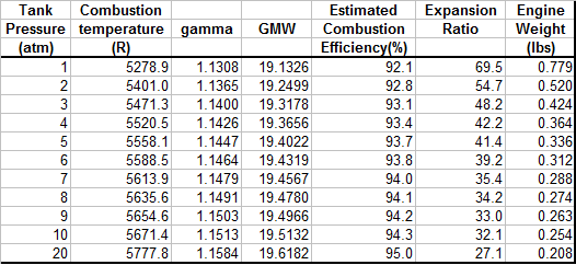
The following graph shows the relationship between Propellant Tank pressure and Combustion Chamber weight. As can be seen, there is an inverse relationship: a higher chamber pressure results in a smaller and lighter combustion chamber.

PROPELLANT TANK
WEIGHT
The propellant tanks are simple pressurized spherical tanks made from the same steel as the combustion chamber. The same maximum stress limit was used.
The following graph shows the weight of the tanks as a
function of their pressure. It shows the obvious trend that the tank weight
increases with pressure.

SUMMARY
The following graph shows the combination of weights from
the various components and their sum. As can be seen, propellant tank weights
and pressurant system weights dominate the overall weight. Although the engine
weight decreases with propellant pressure, it's such a small amount that it is
overshadowed by the effects of propellant tanks and pressurant system weights.

The resulting summary is that the pressure that will result
in the lightest overall stage is the lowest pressure feasible.