Shoe box-size satellites one of the next big things
Boston Globe, 28 November 2011
http://bostonglobe.com/business/2011/11/28/shoe-box-size-satellites-one-next-big-things/mIcNPfU6V7aakZL9lYgihK/story.html
One of the next big things in space innovation is a modest cube, about the size of a coffee mug or a shoe box, now being developed to circle Earth and monitor space weather, observe the atmosphere, and test the feasibility of using a sun-powered sail to tow space junk.
Over the past decade, these diminutive cube satellites, or CubeSats,have grown in importance. Some think they are poised to have a potentially profound impact on the big-budget space industry, where missions can routinely cost hundreds of millions, similar to the effect the advent of personal computers had on computing.
Wednesday, November 30, 2011
Tuesday, November 29, 2011
News: Garvey Spacecraft Awarded NASA Launch Service Contract
Garvey Spacecraft, 19 October 2011
http://www.garvspace.com/2011/PR_2011_01/GSC%20press%20release%202011-01%20-%20NASA%20LSP%20contract%20award.pdf
Garvey Spacecraft Corporation (GSC) announced today that it has been awarded a contract from the NASA Launch Services Program (LSP) at Kennedy Space Center, FL to provide a high altitude launch service for demonstration NanoSatellites.
News: NASA's Nanosail-D 'Sails' Home -- Mission Complete
NASA's Nanosail-D 'Sails' Home -- Mission Complete
NASA, 29 November 2011
http://www.nasa.gov/mission_pages/smallsats/11-148.html
After spending more than 240 days "sailing" around the Earth, NASA's NanoSail-D -- a nanosatellite that deployed NASA's first-ever solar sail in low-Earth orbit -- has successfully completed its Earth orbiting mission.
Launched to space Nov. 19, 2010 as a payload on NASA's FASTSAT, a small satellite, NanoSail-D's sail deployed on Jan. 20.
The flight phase of the mission successfully demonstrated a deorbit capability that could potentially be used to bring down decommissioned satellites and space debris by re-entering and totally burning up in the Earth's atmosphere. The team continues to analyze the orbital data to determine how future satellites can use this new technology.
A main objective of the NanoSail-D mission was to demonstrate and test the deorbiting capabilities of a large low mass high surface area sail.
"The NanoSail-D mission produced a wealth of data that will be useful in understanding how these types of passive deorbit devices react to the upper atmosphere," said Joe Casas, FASTSAT project scientist at NASA's Marshall Space Flight Center in Huntsville, Ala.
Sunday, November 27, 2011
Cubesat Workshop Presentations
Cubesat Workshop Presentations
CalPoly San Luis Obispo, Various
http://mstl.atl.calpoly.edu/~bklofas/Presentations/
Presentations from various years of Cal Poly San Luis Obispo's Cubesat Workshops.
CalPoly San Luis Obispo, Various
http://mstl.atl.calpoly.edu/~bklofas/Presentations/
Presentations from various years of Cal Poly San Luis Obispo's Cubesat Workshops.
Friday, November 25, 2011
News: OpenRocket Version 1.1.9 Released
OpenRocket Version 1.1.9 Released
Open Rocket, 24 November 2011
http://openrocket.sourceforge.net/
For this version Richard Graham has implemented geodetic computation methods, which take into account the curvature of the Earth and the coriolis effect. The computation method is selected by the Geodetic calculations option in the simulation options. It's not (yet) a full spherical computation model, but should be accurate enough for almost all sub-orbital needs.
Wednesday, November 23, 2011
News: SpaceWorks Nanosat Market Study
SpaceWorks Nanosat Market Study
The Space Business Blog, 22 November 2011
http://spacebusinessblog.blogspot.com/2011/11/spaceworks-nanosat-market-study.html
SpaceWorks Commercial today released their latest nano/microsatellite market study. You can download it here. The study is quite bullish on the growth of Nanosatellites over the next decade with over 20% growth per year through 2014.
Tuesday, November 22, 2011
News: Cubesats Move Out Of The Classroom
Cubesats Move Out Of The Classroom
Aviation Week, 22 November 2011
http://www.aviationweek.com/aw/generic/story_channel.jsp?channel=space&id=news/asd/2011/11/22/08.xml&headline=Cubesats%20Move%20Out%20Of%20The%20Classroom
Cubesats — the small, cheap spacecraft popular with engineering students due to their hands-on appeal as teaching tools — are attracting attention beyond the academy as their capabilities grow and launch opportunities proliferate.
News: SpaceWorks Commercial Releases Nano/Microsatellite Launch Demand Assessment
SpaceWorks Commercial Releases Nano/Microsatellite Launch Demand Assessment 2011
SpaceWorks, 22 November 2011
http://www.sei.aero/press/press_2011-11-22.shtml
SpaceWorks Commercial (a division of SpaceWorks Enterprises, Inc.) releases a new study highlighting increasing yearly demand for orbital launch services for the nanosatellite and microsatellite market. The study, entitled “Nano/Microsatellite Launch Demand Assessment 2011” is a quantitative assessment of past launches and a projection of future launch demand up to 2020. Projections indicate more than 100 nano/micro satellites will need launches in the year 2020. A presentation summarizing this assessment is available on the SpaceWorks website.
Monday, November 21, 2011
Video: Beyond Planet Earth The Future of Space Exploration
Beyond Planet Earth: The Future of Space Exploration
American Museum of Natural History, 21 November 2011
http://www.amnh.org/exhibitions/beyond/
The Moon. Mars. An icy moon of Jupiter. A near-Earth asteroid. In the not too distant future, missions to these destinations will launch from Earth.
All would involve countless hours of planning and hard work, opportunity for scientific glory—and risk. But if the missions succeed, what adventures would unfold! Tonight, look up. Above you: the universe.
Sunday, November 20, 2011
Black Arrow: Britains Satellite Launcher
The Black Arrow was Great Britain's first indigenously-developed rocket launcher. In four flights, two were successful. It successfully put one satellite, the Prospero, into orbit, making Great Britain the sixth country to orbit a satellite (after the Soviet Union, the United States, France, Japan and China)
SOURCES
Finding accurate, authoritative information on the Black Arrow was difficult (at least in the U.S.). Therefore, one should expect a wider error margin on the weights and performances listed here. However, the values make sense with regard to various sources so they probably aren't too far off.
Because of the conflicting and non-authoritative information published widely on the Internet, I'm going to approach this discussion a bit differently. Since the Internet references conflict or give obviously wrong information, I'm going to extract some of the design information from highly authoritative sources and first principles, confirming or denying information published from less authoritative sources. Otherwise, I'll use whatever other technical information from other sources
that appears correct with the models derived from more accurate sources.
There are two primary sources that I'll base much of the analysis on. The first is the table of weights [1] published by the Royal Airforce Establishment (RAE).

The second source is a trajectory diagram [2] also published by the RAE. This diagram illustrates the time of launch events and other significant parameters of the orbital ascent.

The problem with the trajectory data diagram that warrants caution is that there is no specific identification of this trajectory with a specific vehicle (there were five of them built) as well as whether or not this diagram represents desired or actual trajectory figures. However, the results obtained by using this diagram match well with the specifications from the weight table. Therefore, I'll use at as a basis for establishing authoritative derived parameters.
GENERAL
The Black Arrow was a three stage satellite launcher able to place a 300 pound (136 kg) satellite into a 135 mile altitude Low Earth Orbit. The first and second stages used liquid propellants and the third stage used a solid motor.
The following table shows the performances and weights of the stages and its constituent components. Because the second stage carried and then jettisoned the payload aerodynamic fairing during flight, it has been broken into two stages, BA2A and BA2B (for before and after fairing separation, respectively):

DETERMINING ACTUAL STAGE SPECIFIC IMPULSES
Most sources, even from the 1960's say that the Specific Impulse (Isp) is 265 seconds for both the first stage and the second stage. This is obviously wrong for several reasons because the first stage flies through a varying atmospheric pressure regime throughout its flight and therefore the Isp will vary. We need to know what the range of Isp variance is to properly model the vehicle. Additionally, although the first and second stage motors were very similar, there were significant differences that affected their performances. Specifically, although the second stage may have used the same motor chambers as the first stage, it has been stated in numerous sources that the second stage had a nozzle extension. This would make the Isp of the second stage different from that of the first. Therefore, I need to look at what realistic Specific Impulses might be for each of the stages.
There is authoritative information that might give clues to the likely performances of the first and second stage motors. Using the two primary sources, I can derive some bounds on the specific impulses of the engines in each stage.
For review, the formula for Isp (Specific Impulse) is:
Isp = Thrust * time / weightWhere the Isp (in seconds) is equal to the thrust (in force) times the number of seconds of that thrust divided by the weight of the propellant (also in force units) required to produce the thrust. Since you have force units over force units in the equation, they cancel out, leaving only seconds as the remaining unit.
The weight table says that the propellant weight of the first stage is 28735 lbs with a thrust of 50000 lb-f at sea level and 57640 lb-f in vacuum. The trajectory diagram says that the first stage burn duration was 131.2 seconds. The propellant weight of 28735 lbs divided by 131.2 seconds means that (on average), the propellant usage rate is 219.017 lbs/sec. Now, I have no idea whether or not the engines were throttled during the flight so it is possible that this only does represent an average usage, and not an actual per-second usage, but it's the best information I have. Based on these numbers and the Isp equation, we can establish that the effective Sea Level Isp is:
 Eff. Isp(SL) = 50,000 lb-f * 1 s / 219.017 lb-m
 Eff. Isp(SL) = 228.293 seconds

 Eff. Isp(VAC) = 57640 lb-f * 1 s / 219.017 lb-m
 Eff. Isp(VAC) = 263.176 seconds
The Weight table lists the second stage as having 6522 lbs of propellant and a vacuum thrust of 15340 lb-f. The trajectory diagram shows the burn time of the second stage as 116 seconds. With 6522 lbs of propellant burnt in 116 seconds, the average propellant usage is 56.224 lb-m/s. Using the Isp equation, we can specify the effective Isp as:
 Eff. Isp(VAC) = 15340 lb-f * 1 s / 56.224 lb-m
 Eff. Isp(VAC) = 272.84 seconds
These answers make a basic kind of sense because the first stage motor's Isp will vary throughout flight up to its maximum Isp performance in a vacuum. The second stage, having a nozzle extension, will have somewhat greater Isp in vacuum.
For the third stage, I could find no authoritative source for the motor efficiency; I used an Isp value which is widely cited on the Internet. The propellant weight values I used are derived from [5].
Whether these estimations are accurate representations of the actual usage or not, I can't say. But, a rocket which has these parameters would closely meet the basic performance characteristics specified in the reference documents.
FIRST STAGE
The first stage utilized a Gamma-8 type rocket motor which burned 90% Hydrogen Peroxide and Kerosene. The Gamma 8 consisted of 8 separate chambers in a cruciform shape which gimballed on one axis each. These were fed through a peroxide-driven turbopump which raised the chamber pressure to about 640 PSI (reported as 44 bar/638 PSI in several sources but as high as 47.4 bar/687 PSI in other sources). Each chamber had an expansion ratio of about 10 giving them good high altitude performance: a Sea Level Isp of about 228 seconds and a vacuum Isp of about 265 seconds.
Regarding the Gamma-8 motors, various sources say that they had expansion ratios anywhere from 60 to 80. However, no motor running at sea level will have stable exhaust if the exit exhaust pressure is below about 40% of the atmospheric pressure. With a chamber pressure of 640 PSI, the exhaust pressure of a 60:1 nozzle will be about 1 PSI versus the 14.7 PSI atmospheric pressure. Sixty-to-one or greater appears to be too high of an expansion ratio for the first stage motors. Historical sources tell us that the Gamma-8 motor chambers were derived from the Gamma 301. A cross sectional diagram of the Gamma 301 is available in [4]:
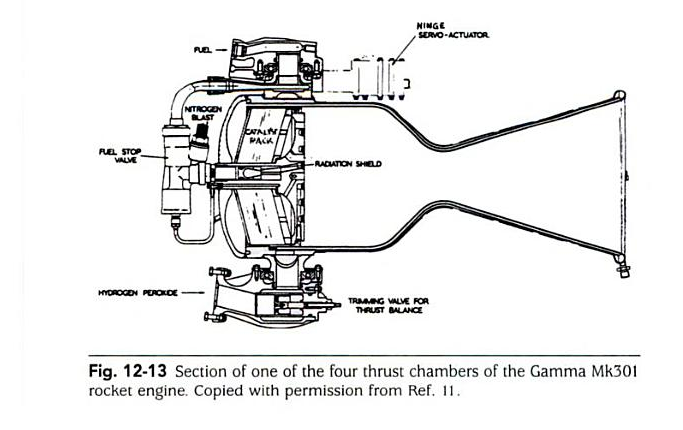
Measuring the Gamma-301 ratio of the diameters (squared) of the nozzle exit versus the throat shown in this picture gives an area ratio of 10.27. All pictures of the first stage motors appear to have this ratio in all pictures that I've seen. Therefore, I reject the various claims that the first stage motors had an expansion ratio of 60, 80 or more. The expansion ratio appears to be about 10 which is consistent with exhaust stability theory, the computed Isp's and various images of the motors.

If I model the motors using a combustion analysis program with the published values, then I get the following results:

These values very closely match the values derived by using the flow rates and thrusts. So, if the motors ran closer to 100% efficiency and the turbopumps used about 6% of the calculated efficiency to operate, then we would see the kinds of Isp values that I've calculated.
SECOND STAGE
The second stage used two of the same chambers that made up the 8 motors of the Gamma-8. A nozzle extension was added to the motors to give a reported expansion ratio of 350:1 (according to some sources). These motors are reported as having a vacuum Isp of 265 seconds but my analysis shows it's likely closer to 273 seconds.
The second stage carried the payload fairing. The trajectory table shows the payload fairing being ejected after 180 seconds. The weight of the fairing can be found in the weight table[1].
For the second stage motor, there does not appear to be any authoritative source referencing the expansion ratio of the nozzle. But using the 94% combustion efficiency derived for the first stage, and the derived value of the vacuum Isp as being 272.84 seconds, then the motor maximum theoretical Isp would have to be something like 272.84 s / 0.94 or 290.26 seconds. Again using a combustion analysis software, and the pressure and mixture ratios used in the first stage motors, we can estimate that the second stage expansion ratio had to be at least 16:1 as the minimum necessary expansion ratio. The various pictures of the second stage nozzles seem to suggest that the nozzle expansion ratio may have been closer to 60 or 80. Maybe this was the value that was wrongly attributed to the first stage expansion ratio in the various sources. As it stands, I have no idea what the accurate expansion ratio was.
THIRD STAGE
The third stage used a solid propellant rocket motor (called Waxwing) without guidance but which was spun to be gyroscopically stabilized. Again, sparse authoritative information exists for its specifications.
GUIDANCE AND CONTROL
Like the few rockets we have looked at so far, the guidance system was kept in the second stage, and the third stage was unguided. Using the familiar "point and fire" technique, the second stage would orient itself to the desired angle for the orbit, small rockets were used to spin up the third stage to ensure orientation stability and then the third stage would fire its motor.
The first stage control system utilized motor gimbaling to provide full yaw-pitch-roll control. The second stage also utilized gimbaling of two motors to provide full control during motor firing. After the second stage propellant was burned out, the second stage used a pressurized nitrogen cold-gas reaction control system to orient the third stage for firing.
AERODYNAMIC AND GRAVITATIONAL LOSSES
Simulations using the specifications above result in an observed first stage aerodynamic loss of 587 feet per second (fps) and gravitational losses of about 4218 fps. The reason for these kinds of losses are due to the Black Arrow's relatively large diameter relative to its length (it had a fineness ratio of 7) and its relatively low acceleration (takeoff thrust was only 25% more than GLOW).
SUMMARY
I can't say how accurate these results are, but they fit and describe the vehicle fairly well. A vehicle with the specifications described above would have similar performance to those described in the various sources. Nonetheless, the derived specifications are still useful metrics for comparison against other vehicles.
REFERENCES
[1] Weight Table, derived from reference [3] page 28.
[2] Trajectory Table, derived from reference [3] page 50.
[3] The Black Arrow rocket: a history of a satellite launch vehicle and its engines
    Millard Douglas, 2001, ISBN 1900747413
[4] History of Liquid Propellant Rocket Engines
    Sutton George Paul, 2006, ISBN 1563476495
[5] A Vertical Empire
    Hill C.N., 2001, ISBN 1-86094-267-9
Friday, November 18, 2011
Video: Team Phoenicia Nanosat Launcher Challenge Seminar
Nanosat Launcher Challenge Seminar: Team Phoenicia as a Supplier and How to Get Sponsorships
YouTube, 15 November 2011
http://www.youtube.com/user/teamphoenicia#p/a/u/0/ijXuEK8VwPI
William Baird Team, Leader of Team Phoenicia, presents on how Team Phoenicia contracts out (first part of the talk) and how to get sponsorships (second part).
YouTube, 15 November 2011
http://www.youtube.com/user/teamphoenicia#p/a/u/0/ijXuEK8VwPI
William Baird Team, Leader of Team Phoenicia, presents on how Team Phoenicia contracts out (first part of the talk) and how to get sponsorships (second part).
Video: Hand Made Mini V12 Engine
Hand Made Mini V12 Engine
LiveLeak, 18 November 2011
http://www.liveleak.com/view?i=fd8_1321653527
Not rockets, but very neat...
Very detailed V12 motor. This video shows some of the manufacturing and some of the assembly.
LiveLeak, 18 November 2011
http://www.liveleak.com/view?i=fd8_1321653527
Not rockets, but very neat...
Very detailed V12 motor. This video shows some of the manufacturing and some of the assembly.
News: Blue Origin spruces up rocket report
Blue Origin spruces up rocket report
Cosmic Log, 18 November 2011
http://cosmiclog.msnbc.msn.com/_news/2011/11/18/8871807-blue-origin-spruces-up-rocket-report
Blue Origin, the secretive rocket venture founded by Amazon.com billionaire Jeff Bezos, has unveiled a spruced-up website that includes videos of its successful "short hop" flight test back in May.
News: Rocket Racing League backs off Melbourne plan
Rocket Racing League backs off Melbourne plan
Florida Today, 17 November 2011
http://www.floridatoday.com/article/20111118/NEWS01/311180024/Rocket-Racing-League-backs-off-Melbourne-plan
The fledgling Rocket Racing League is no longer considering moving its headquarters from Orlando to Melbourne International Airport, said Mike D’Angelo, chief operating officer.
Tuesday, November 15, 2011
News: US student to fill heavens with Sprites
US student to fill heavens with Sprites
The Register, 15 November 2011
http://www.theregister.co.uk/2011/11/15/sprite_project/
A Cornell University postgrad student is offering enthusiasts the chance to get their own diminutive bit of kit into space, in the form of a miniature satellite.
Zac Manchester's Sprite is a solar-powered board "about the size of a couple of postage stamps", which packs a "microcontroller and a radio for communicating with ground stations from low Earth orbit".
News: XCor Contest for a Lynx Suborbital Flight
XCOR NSRC-2012 Research/Education Flight Prize
XCor, 15 November 2011
http://www.xcor.com/NSRC-2012-contest-rules/
Open to Earlybird Professional, Advanced Professional, or Advanced Student Paid Registration (Onsite and One-Day Registrations are not eligible) prior to 0830AM PT 26 February 2012 of the Next-Generation Suborbital Researchers Conference 2012 (NSRC-2012) who are: legal residents of countries not on the US State Department’s Country Policies and Embargoes List and where this contest is deemed legal by the governmental authorities, 18 years of age or older as of date of registration, a paid registrant at NSRC-2012, and satisfy other qualifications as found in the Official Rules and any XCOR or government rules, laws or regulations required to fly an experiment on the Lynx Mark I suborbital spacecraft.
News: UK Space Agency OKs teeny-tiny satellite
UK Space Agency OKs teeny-tiny satellite
The Register, 8 November 2011
http://www.theregister.co.uk/2011/11/08/ukube_1_design_approved/
"The UK Space Agency has approved the design of UKube-1, the UK's first CubeSat mission.
Last week, a team of engineers from Clyde Space, a microspacecraft maker, submitted their design for the UKube-1 to be reviewed by a team of experts, who concluded that the design was sound."
Thursday, November 10, 2011
The Scout Launch Vehicle
The Scout was an all solid rocket motor launch vehicle. It was one of the smallest and earliest launchers developed by NASA, used for payloads less than about 550 lbs into low Earth orbit (LEO). Its development began in 1957 and its first test launch was in 1960, just 2 years after the US launched the Explorer satellite. The first Scout successfully placed a payload into orbit in 1961. The Scout family of rockets had a long lifespan of over 30 years with 118 launches and the last one being launched in 1994.

There's a lot of information on the Scout launch vehicle available on the web, and there were many different variants over the years with payload capabilities from a few pounds up to 550 pounds. I will only concentrate on aspects relevant to the discussion of developing small launchers.
GENERAL
The Scout was a four stage all-solid propellant vehicle (except that liquids were used for orientation control of the upper stages). The first stage was an Algol motor which used aerodynamic fins and jet vanes in the rocket motor exhaust stream for control. The second stage was a Castor motor which used hydrogen peroxide reaction control rockets for guidance and orientation. The third stage was an Antares motor which also used hydrogen peroxide reaction control rockets for orientation. The fourth stage used an Altair motor which was unquided but spun on its long axis for orientation stability.

GUIDANCE AND CONTROL
It is worth focusing on the guidance and control approach used on the Scout vehicles since it has lessons for those designing small launch vehicles. First, the guidance and control system of the Scouts was a relatively simple pitch rate system controlled by a timer. The roll and yaw axes used a gyro system to ensure that the vehicle maintained a specific roll and yaw attitude throughout its flight. This reduced the guidance problem from three rotational orientation dimensions down to a one-dimensional pitch over problem. Clockwork mechanisms used pre-programmed pitch rates to ensure that the vehicle had the proper pitch throughout the flight to orbit. At the end of the third stage flight, spin rocket motors spun up the fourth stage to provide it some amount of orientation stability. Then the fourth stage motor was ignited to add the last amount of delta V required to get the payload to orbit. Like other small launchers, the final stage was unguided and the lower stages were responsible for orienting it before firing.
MASS CONSIDERATIONS
We can also learn something by considering the side effects necessary to take a raw motor and turn it into a useful stage. For the following analysis, I will consider the Scout D configuration.
The first stage of the Scout D used a Algol III motor. In its basic configuration, the motor weighs 31305.10 pounds and has a total propellant weight of 28,059.77 pounds. Subtracting the propellant from the total weight leaves an inert weight of about 3245.33 pounds. This results in an inert:propellant ratio of 0.116. However, if we look at the stage weights of the first stage, we see that its inert weight is 4211.37 pounds. Therefore, the control system (which includes fins, jet vanes and other hardware) adds about 966.04 pounds resulting in a stage inert:propellant ratio of 0.1489. So, the inert weight increased from 3245.33 lbs to 4211.37 lbs for a weight increase of 130 % (30% more weight for the control system).
The second stage of the Scout D used a Castor IIA motor. In its basic configuration, the motor weighs 9774.26 pounds and has a total propellant weight of 8206.15 pounds. Subtracting the propellant from the total weight leaves an inert weight of about 1568.11 pounds. This results in an inert:propellant ratio of 0.1911. Looking at the full second stage weight, however, we see that the stage inert weight is 2399.06 pounds. Therefore, the control system and staging mechanisms of this stage weighs about 831.49 lbs resulting in a stage inert:propellant ratio of 0.2891. So, the inert weight increased from 1568.11 to
2399.06 lbs for a weight increase of 153 % (50% more weight for control and staging systems).
The third stage of the Scout D used an Antares II motor. In its basic configuration, the motor weighs 2796.80 pounds and has a total propellant weight of 2559.43 pounds. Subtracting the propellant from the total weight leaves an inert weight of about 237.37 pounds. This results in an inert:propellant ratio of 0.0927. Looking at the stage weight, though, we see that the stage inert weight is 771.95 pounds. Therefore, the control system and staging mechanisms added about 534.58 pounds with a resulting stage inert ratio of 0.2982. The staging and control system added 534.48 lbs to the motor's 237.37 lbs and thus added 225 percent (or 125 percent increase) to this stage.
The fourth and final stage of the Scout D used an Altair III motor which weighs 666.63 pounds full and has 607.15 pounds of propellant; the inert weight is thus 59.48 pounds for an inert:propellant ratio of 0.0980. The third stage inert weight is 104.62 lbs, 45.14 lbs worth of staging mechanism (since there is no control system). This is an increase of 176% (or 76% increase) just for staging mechanisms.
Although this section might seem like just a bunch of useless weight breakdowns and percentages, it is sometimes good to know these percentages to provide a grounded estimate of control system weight increase. One trend that might be noticed is that as we go up the stages, the mass of the control and staging mechanisms become a higher percentage of the stage weight. This is because it's not always easy to scale these down equally with the stages. This issue is especially significant for smaller launch vehicles.
AERODYNAMIC AND GRAVITY LOSSES
Just to be complete and provide some basis for comparison, I will give my estimate of the aerodynamic and gravity losses.
Because the Scout had a high fineness ratio (length to diameter ratio) of about 20, it had relatively low aerodynamic losses. Of course, the trajectory and other factors affect the overall aerodynamic losses and gravity losses, but using a simulation close to that of the Scout 185C, my simulations show that the aerodynamic losses were about 327.76 fps and gravity losses were about 2640.40 fps for the first stage.
LESSONS THAT ONE MIGHT LEARN
There are three major lessons that I think are worth learning from the Scout family of rocket launchers. First, it is possible to have an orbital rocket launcher which uses only simple one-degree pitch control guidance (once the other two axes are stabilized). Second, it is possible to have no guidance in the final stage. Third, it is possible to have orbital rockets with length to diameter ratios of 20 or more at lift-off. These facts provide some credibility for smaller orbital rocket designs that might also utilize these design techniques.
REFERENCES
Scout: The Unsung Hero of Space
YouTube http://www.youtube.com/watch?v=btRk6AhoOmI
Scout Launch Vehicle Program, Part 2, Phase 6 Final Report
NASA, 19820073029_1982073029.pdf
Project Development Plan: Scout Program
NASA, 19810069924_19810069924.pdf
News: Space Shuttle's Last Satellite Gets Hobby Rocket Boost
Space Shuttle's Last Satellite Gets Hobby Rocket Boost
Rocketry Planet, 7 November 2011
http://www.rocketryplanet.com/index.php?option=com_content&task=view&id=3706&Itemid=30#axzz1dGeK2tPX
"To ensure mission longevity, four small thrusters were included on the spacecraft, each using the propellant grain and nozzle assembly from an Aerotech E28T rocket motor. On November 4th, the first of these motors was fired to raise the orbit and increase the mission duration."
Sunday, November 6, 2011
News: Launch Magazine Online
Launch Magazines Online
Launch, 6 November 2011
http://www.launchmagonline.com/
Several back issues of Launch magazine are available online at the website. From the webpage:
"LAUNCH Magazine was created in 2006 to celebrate spaceflight and the hobbies inspired by it. The magazine was published from September 2006 through December 2008. It included interviews with current and former astronauts, scientists and visionaries in all aspects of spaceflight and aerospace. The issues also included a wide range of hobby rocketry articles, including coverage of major national competitions as well as model construction techniques, and historically-important interviews with pioneers of the hobby."
News: Small Satellites Prompt Big Ideas for Next 25 Years
Small Satellites Prompt Big Ideas for Next 25 Years
Space.com, 17 October 2011
http://www.space.com/13283-small-satellites-cubesats-research-technology.html
Call them a powerful force in the universe. Smallsats have already shown their ability to monitor disasters, study Earth’s environment and support agriculture, cartography and earth science missions.
Thursday, November 3, 2011
Moon 2.0: A Beautiful Launch Simulator
Moon 2.0
http://code.google.com/p/moon-20/downloads/list
Check out the Moon 2.0 launch simulator. It's a beautiful program to simulate a launch vehicle. Because it's open source, you can adapt it to just about any need.
I have been playing with it with known performance simulations, but have yet to have it generate accurate trajectories. However, as I study this program, I see it is possible to add custom data files and I'll be experimenting with trying to get accurate trajectories from various designs.
Tuesday, November 1, 2011
News: Nanosat Challenge Allied Organization Selected
NASA And Space Florida Small Satellite Research Center Partner In Space Launch Challenge
NASA, 1 November 2011
http://www.nasa.gov/home/hqnews/2011/nov/HQ_11-370.html
NASA has signed an agreement with the Space Florida Small Satellite Research Center of Cape Canaveral, Florida, to manage the Nano-Satellite Launch Challenge, one of the agency's new Centennial Challenges prize competitions.
The Nano-Satellite Launch Challenge is to launch satellites with a mass of at least 2.2 pounds (1 kg) into Earth orbit, twice within the span of one week. The new challenge has a NASA-provided prize purse of $2 million.
The objective of the competition is to encourage innovations in propulsion and other technologies, as well as operations and management relevant to safe, low-cost, small payload delivery system for frequent access to Earth orbit. Innovations stemming from this challenge will be beneficial to broader applications in future launch systems. They may enhance commercial capability for dedicated launches of small satellites at a cost comparable to secondary payload launches -- a potential new market with government, commercial, and academic customers.
News: Cube-Sats - small satellites for the common man
Cube-Sats - small satellites for the common man
Las Crucas Sun-News, 31 October 2011
http://www.lcsun-news.com/las_cruces-news/ci_19237059
"Here is a great accomplishment: Montana State University, Auburn, Utah State and Michigan State launched Cube-Sat satellites on Oct. 28 at 5:30 a.m. You can watch the launch at www.cubesat.org. The satellites are launched in the same launcher, called a P-POD (Poly Picosatellite Orbital Deployer). The Cube-Sats are 10x10x10 cm in size."
Subscribe to:
Posts (Atom)